Method of generating monodisperse emulsions

a monodisperse and emulsion technology, applied in the field of generating monodisperse emulsions, can solve the problems of preventing the implementation of new, useful droplet techniques, and affecting the use of droplet microfluidics by researchers, and preventing the effect of affecting the use of droplet microfluidics

Pending Publication Date: 2020-08-20
RGT UNIV OF CALIFORNIA
View PDF0 Cites 11 Cited by
  • Summary
  • Abstract
  • Description
  • Claims
  • Application Information

AI Technical Summary

Benefits of technology

[0004]The methods described herein, referred to as particle-templated emulsification (PTE), provide an improved approach for generating a monodisperse emulsion that encapsulates target particles of interest without requiring the use of a microfluidic device. The present disclosure is based in part on the surprising discovery that monodisperse droplets may be effectively obtained by using monodisperse particles to template the formation of droplets, which can include, e.g., monodisperse single-emulsion droplets, multiple-emulsion droplets, or Giant Unilamellar Vesicles (GUV) (also referred to herein as liposomes), without destroying the integrity of the droplets.
[0006]In some embodiments, the target particles may include a heterogeneous population of cells, viruses, and / or nucleic acids. In some embodiments, the target particles may be diluted prior to encapsulation, e.g., so as to encapsulate a controlled number of cells, viruses, and / or nucleic acids in the monodisperse droplets. Nucleic acid synthesis reagents, e.g., isothermal nucleic acid amplification reagents, non-specific nucleic acid amplification reagents (e.g., MDA reagents), and / or PCR reagents, may be co-encapsulated in the monodisperse droplets, e.g., along with one or more target particles, or added to the monodisperse droplets at a later time using one or more of the methods described herein to facilitate downstream detection, sorting, and / or analysis as described herein.
[0009]Monodisperse template particles for use in methods as described herein may be generated, for example, by flowing a first fluid, e.g., a liquid gel precursor, in a channel of a microfluidic device; and contacting the first fluid with a second fluid, wherein the second fluid is immiscible with the first fluid, e.g., using a single-emulsion droplet maker. In some embodiments, parallel droplet generation techniques including serial splitting and distribution plates can be used to form the monodisperse template particles more rapidly. The monodisperse single-emulsion droplets are then solidified by triggering gelation, e.g. polymerizing the gel matrix within the droplets or crosslinking the matrix. In some embodiments, a surfactant may be used to prevent contacting monodisperse template particles from coalescing with each other. One or more steps of the method for generating monodisperse template particles may be performed under microfluidic control.
[0013]As described herein, the term “next-generation sequencing” generally refers to advancements over standard DNA sequencing (e.g., Sanger sequencing). Although standard DNA sequencing enables the practitioner to determine the precise order of nucleotides in the DNA sequence, next-generation sequencing also provides parallel sequencing, during which millions of base pair fragments of DNA can be sequenced in unison. Standard DNA sequencing generally requires a single-stranded DNA template molecule, a DNA primer, and a DNA polymerase in order to amplify the DNA template molecule. Next-generation sequencing facilitates high-throughput sequencing, which allows for an entire genome to be sequenced in a significantly shorter period of time relative to standard DNA sequencing. Next-generation sequencing may also facilitate in identification of disease-causing mutations for diagnosis of pathological conditions. Next-generation sequencing may also provide information on the entire transcriptome of a sample in a single analysis without requiring prior knowledge of the genetic sequence.

Problems solved by technology

However, the general requirement of microfluidics for droplet encapsulation is a significant barrier to most researchers who rarely have access to advanced microfluidic systems.
The inability to immediately translate droplet microfluidic advances to researchers impedes the implementation of new, useful droplet techniques.
Further, droplets may or may not be stabilized by surfactants and / or particles.

Method used


Image

  • Method of generating monodisperse emulsions
  • Method of generating monodisperse emulsions
  • Method of generating monodisperse emulsions

Examples


example 1

g Monodisperse Single Emulsions Using Particle-Templated Emulsification (PTE)

Results

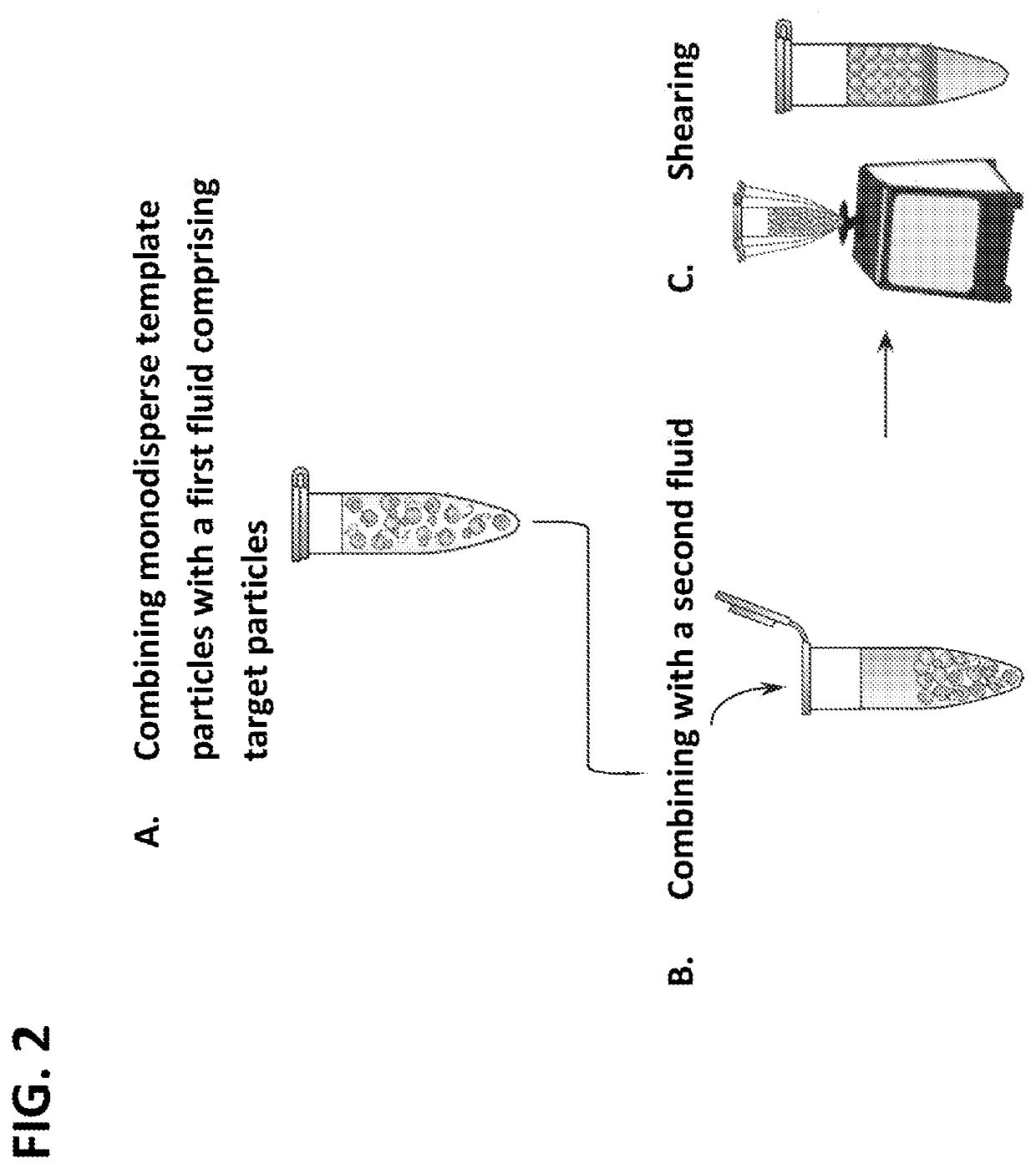
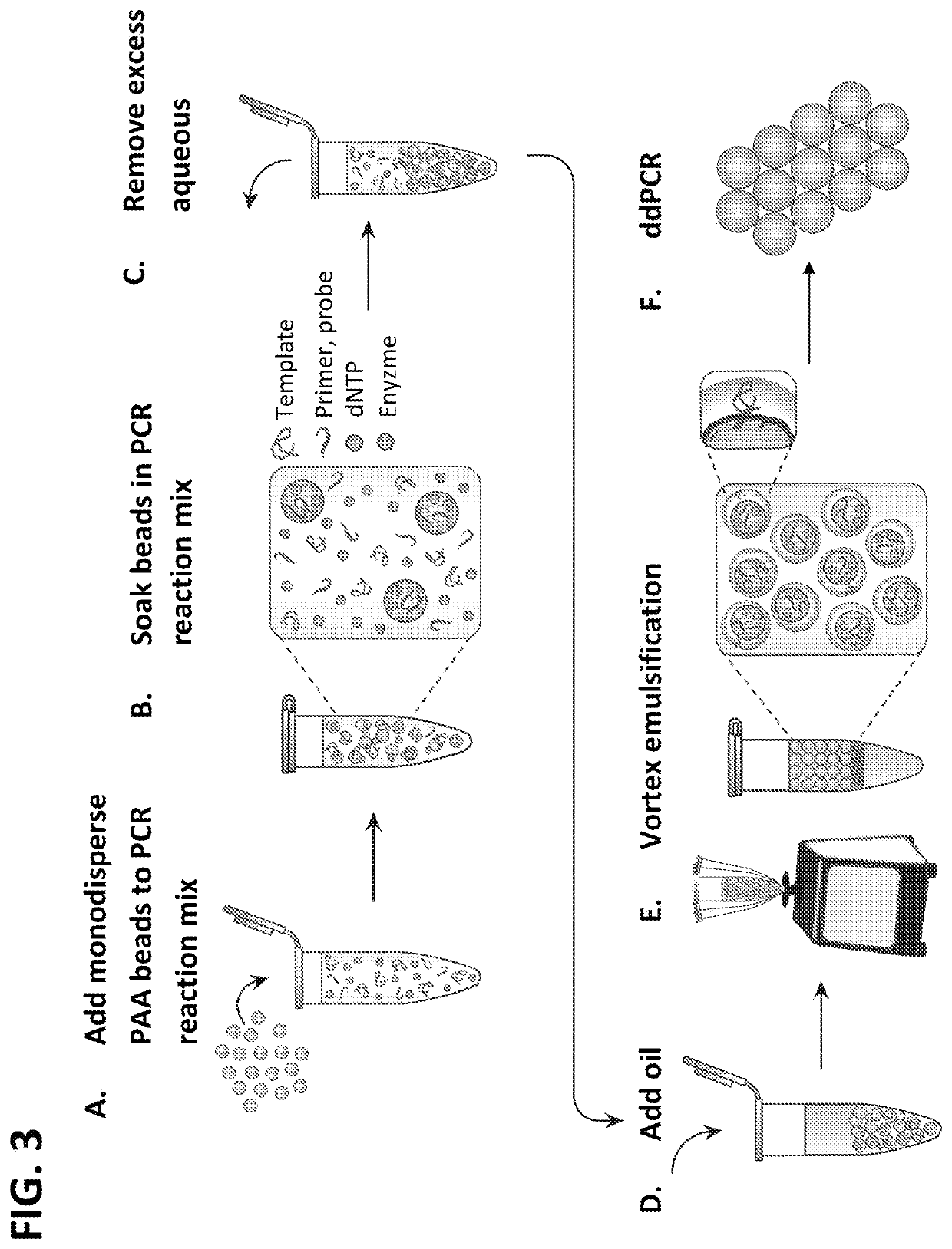
[0334]Hydrogel particles that were greater than 95% aqueous were used for the templating, so that the final droplet was mostly aqueous, as needed for performing biochemical reactions in the resultant droplets. The particles were added to the solution to be encapsulated, with oil and surfactant, and the mixture vortexed (FIG. 2, Panels A-C and FIG. 3, Panels A-E). The hydrogel particles were permeable to molecules with hydraulic diameters smaller than the pore size, like small molecules, but were impermeable to large molecules, such as genomic DNA, which remained within the thin layer of aqueous solution surrounding the particles in the droplets. During vortexing, the particles were dispersed into continually smaller droplets until each droplet contained just one particle and a thin shell of aqueous solution, as illustrated in (FIG. 3, Panel E). Beyond this, further droplet breakup was suppressed beca...

example 2

g Particle Templated Emulsification

Results

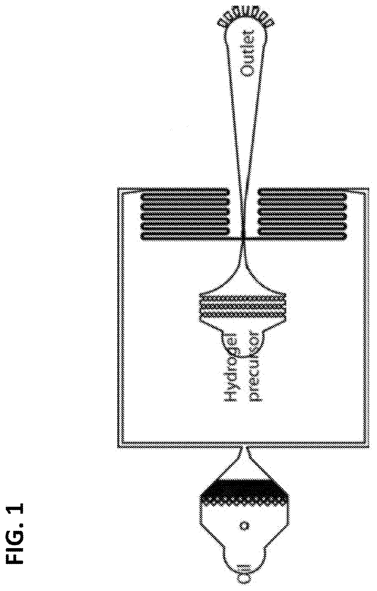
[0336]While emulsions prepared by vortexing in the absence template particles were easily prepared, such emulsions were polydisperse and of limited value for precision biology (FIG. 4, Panel A). As shown in FIG. 4, Panel A (left), vortexed emulsions with no particles generated polydisperse droplets having varied size distribution, 8-218 μm in diameter (n=561) and 4.3% of droplets are 35-40 μm. On the other hand, microfluidic emulsions required specialized devices and skill, but exhibited superior monodispersity and were highly valuable (FIG. 4, Panel A). As shown in FIG. 4, Panel A (right), microfluidics emulsion generated monodisperse droplets: 95.7% of droplets are 35-38 μm in diameter (n=816). An improved method for sample encapsulation would, thus, combine the simplicity of vortexing with the quality of microfluidics.

[0337]PTE accomplished this by exploiting the rigidity of particles to resist droplet breakup below the particle size, eve...

example 3

ed Accurate DNA Quantification with Digital Droplet PCR (ddPCR)

Results

[0346]PTE allowed facile, microfluidics-free ddPCR. To illustrate this, PTE was used to encapsulate several DNA samples at different concentrations of a target molecule (FIG. 8, Panel A). Just as in microfluidic ddPCR, increasing target concentration increased the number of fluorescent droplets. To determine whether this allowed concentration estimation, conventional ddPCR analysis was followed and droplet fluorescence quantified using imaging, plotting the results as fluorescence versus diameter (FIG. 8, Panel B). Three droplet populations were visible, at low fluorescence and small diameter (satellite droplets), at the expected 30-40 μm diameter and low fluorescence (PCR-negative), and a similar size range but high fluorescence (PCR-positive). The satellite droplets were ignored and the target concentration for the correctly-sized droplets modelled via Poisson statistics,

[0347]λ=−ln(1−p), where λ is the template...


PUM

PropertyMeasurementUnit
diameteraaaaaaaaaa
diameteraaaaaaaaaa
diameteraaaaaaaaaa

Abstract

The methods described herein, referred to as particle-templated emulsification (PTE), provide an improved approach for generating a monodisperse emulsion that encapsulates target particles of interest without requiring the use of a microfluidic device. Monodisperse droplets may be effectively obtained by using monodisperse particles to template the formation of droplets, which can include, e.g., monodisperse single-emulsion droplets, multiple-emulsion droplets, or Giant Unilamellar Vesicles (GUV), without destroying the integrity of the droplets.

Description

CROSS REFERENCE[0001]This application claims the benefit of U.S. Provisional Patent Application No. 62 / 565,976, filed Sep. 29, 2017, which application is incorporated herein by reference in its entirety.GOVERNMENT SUPPORT[0002]This invention was made with government support under grant nos. AR068129, R01 EB019453 and R21 HG007233 awarded by the National Institutes of Health; grant no. HR0011-12-C-0065 by the Defense Advanced Research Projects Agency; and grant no. DBI1253293 awarded by the National Science Foundation. The government has certain rights in the invention.INTRODUCTION[0003]Droplet microfluidics advances laboratory automation by reducing reaction volumes to picoliters and increasing processing to kilohertz. Microfluidic devices form, process, and sort droplets suspended in a carrier fluid; each droplet affords an isolated “test tube” in which a reaction can be performed. The throughput of the approach, combined with the tiny reagent consumption, provide unprecedented pot...

Claims


Application Information

Patent Timeline
Patent Type & Authority Applications(United States)
IPC IPC(8): B01J13/08C12Q1/6869C12Q1/6844B01F17/00C09K23/00
CPCB01J13/08B01F17/0021C12Q1/6844C12Q1/6869B01J13/04A61K9/107A61K9/127A61K47/34A61K9/5015A61K9/5089C12N15/1075C09K23/00C09K23/42
Inventor ABATE, ADAM R.HATORI, MAKIKO N.LIU, LEQIANKIM, SAMUELMODAVI, CYRUS
Owner RGT UNIV OF CALIFORNIA
Why Eureka
Try Eureka