Solid-State Battery Electrolyte Having Increased Stability Towards Cathode Materials

a solid-state battery and electrolyte technology, applied in the field of solid-state battery electrolyte having increased stability towards cathode materials, can solve the problems of inability to meet advanced battery concepts, flammability and flammability of liquid utilized in soa li-ion batteries, and inability to demonstrate large-scale manufacturing, etc., to achieve high ionic conductivity, low cost, and stability towards metallic lithium, and the effect of high ionic conductivity

Pending Publication Date: 2020-09-03
RGT UNIV OF MICHIGAN
View PDF0 Cites 2 Cited by
  • Summary
  • Abstract
  • Description
  • Claims
  • Application Information

AI Technical Summary

Benefits of technology

[0061]LLZO is one of the most attractive solid electrolytes for all solid-state batteries. Al:LLZO (LLZO doped with aluminum to stabilize the cubic crystal structure at room temperature) is attractive due to low cost, high ionic conductivity, and stability towards metallic lithium. To produce an oxide-based composite cathode, a mixture of cathode particles, electrolyte particles, and optionally conductive additive particles must be co-sintered at temperatures of 20° C. to 1400° C. for densification. Our work on composite cathodes has revealed a distinct mechanism whereby Al:LLZO reacts during co-sintering with common cathode materials, such as lithium cobalt oxide (LCO) and lithium nickel cobalt manganese oxide (NMC). Reaction of the aluminum with the cathode material leaves the LLZO undoped and susceptible to lithium uptake. The result is the conversion of the cubic LLZO (la-3d space group) structure to the tetragonal LLZ...

Problems solved by technology

Currently, the liquid electrolyte used in SOA Li-ion batteries is not compatible with advanced battery concepts, such as the use of a lithium metal anode or high voltage cathodes.
Furthermore, the liquid utilized in SOA Li-ion batteries is flammable and susceptib...

Method used


Image

  • Solid-State Battery Electrolyte Having Increased Stability Towards Cathode Materials
  • Solid-State Battery Electrolyte Having Increased Stability Towards Cathode Materials
  • Solid-State Battery Electrolyte Having Increased Stability Towards Cathode Materials

Examples


example

[0100]The following Example has been presented in order to further illustrate the invention and is not intended to limit the invention in any way.

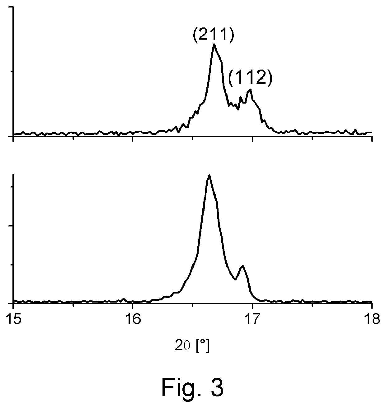
[0101]We have shown that replacement of the Al:LLZO (LLZO doped with Al to stabilize the cubic crystal structure at room temperature) with that of pentavalently doped LLZO, such as Ta:LLZO (LLZO doped with Ta to stabilize the cubic crystal structure at room temperature) or Nb:LLZO (LLZO doped with Nb to stabilize the cubic crystal structure at room temperature) prevents reaction of the LLZO electrolyte with the cathode phase. As such, the LLZO retains the cubic-LLZO structure at room temperature which is desirable for high lithium ion conductivity. Whereas Al:LLZO is unstable during co-sintering with NMC or LCO at 700° C., Ta:LLZO or Nb:LLZO are stable with both cathodes to processing temperatures >1000° C. This innovation is key in enabling processing of LLZO based composite cathodes for all solid-state batteries.

[0102]FIG. 3 gives a plot...


PUM

PropertyMeasurementUnit
Temperatureaaaaaaaaaa

Abstract

Disclosed are electrochemical devices, such as lithium ion battery electrodes, lithium ion conducting solid-state electrolytes, and solid-state lithium ion batteries including these electrodes and solid-state electrolytes. Also disclosed are composite electrodes for solid state electrochemical devices. The composite electrodes include one or more separate phases within the electrode that provide electronic and ionic conduction pathways in the electrode active material phase. A method for forming a composite electrode for an electrochemical device is also disclosed. One example method comprises (a) forming a mixture comprising (i) a lithium host material, and (ii) a solid-state conductive material comprising a ceramic material having a crystal structure and a dopant in the crystal structure; and (b) sintering the mixture, wherein the dopant is selected such that the solid-state conductive material retains the crystal structure during sintering with the lithium host material.

Description

CROSS-REFERENCES TO RELATED APPLICATIONS[0001]This application claims priority to U.S. Patent Application No. 62 / 582,553 filed Nov. 7, 2017.STATEMENT REGARDING FEDERALLY SPONSORED RESEARCH[0002]This invention was made with government support under grant DE-AR0000653 awarded by the Department of Energy. The government has certain rights in the invention.BACKGROUND OF THE INVENTION1. Field of the Invention[0003]This invention relates to electrochemical devices, such as lithium ion battery electrodes, and solid-state lithium ion batteries including these electrodes and solid-state electrolytes. This invention also relates to methods for making such electrochemical devices. In particular, the invention relates to a composite electrode for a solid state electrochemical device wherein the electrode provides electronic and ionic conduction pathways in the electrode active material phase.2. Description of the Related Art[0004]Lithium ion (Li-ion) battery technology has advanced significantl...

Claims


Application Information

Patent Timeline
IPC IPC(8): H01M10/0562H01M10/0525H01M10/0567H01M4/04H01M4/525H01M4/505H01M4/131H01M4/134H01M4/36C04B35/499
CPCH01M4/525H01M10/0567C04B35/499H01M4/131H01M4/0471H01M4/134H01M10/0562H01M10/0525H01M4/505H01M4/364C04B2235/3255B32B18/00C04B35/01C04B35/486C04B35/50C04B2235/3203C04B2235/3227C04B2235/3244C04B2235/3251C04B2235/764C04B2237/34C04B2237/348H01M4/485H01M4/5825H01M2004/028H01M4/624H01M2004/027H01M4/587H01M2300/0071H01M10/052Y02E60/10C04B2235/80C04B2235/3256C04B2235/326C04B2235/3258C04B2235/3293C04B2235/3294C04B35/51C04B35/16C04B35/453C04B35/495H01M4/13H01M4/62H01M4/625H01M4/139
Inventor SAKAMOTO, JEFFREYTHOMPSON, TRAVISTAYLOR, NATHAN
Owner RGT UNIV OF MICHIGAN
Why Eureka
Try Eureka