
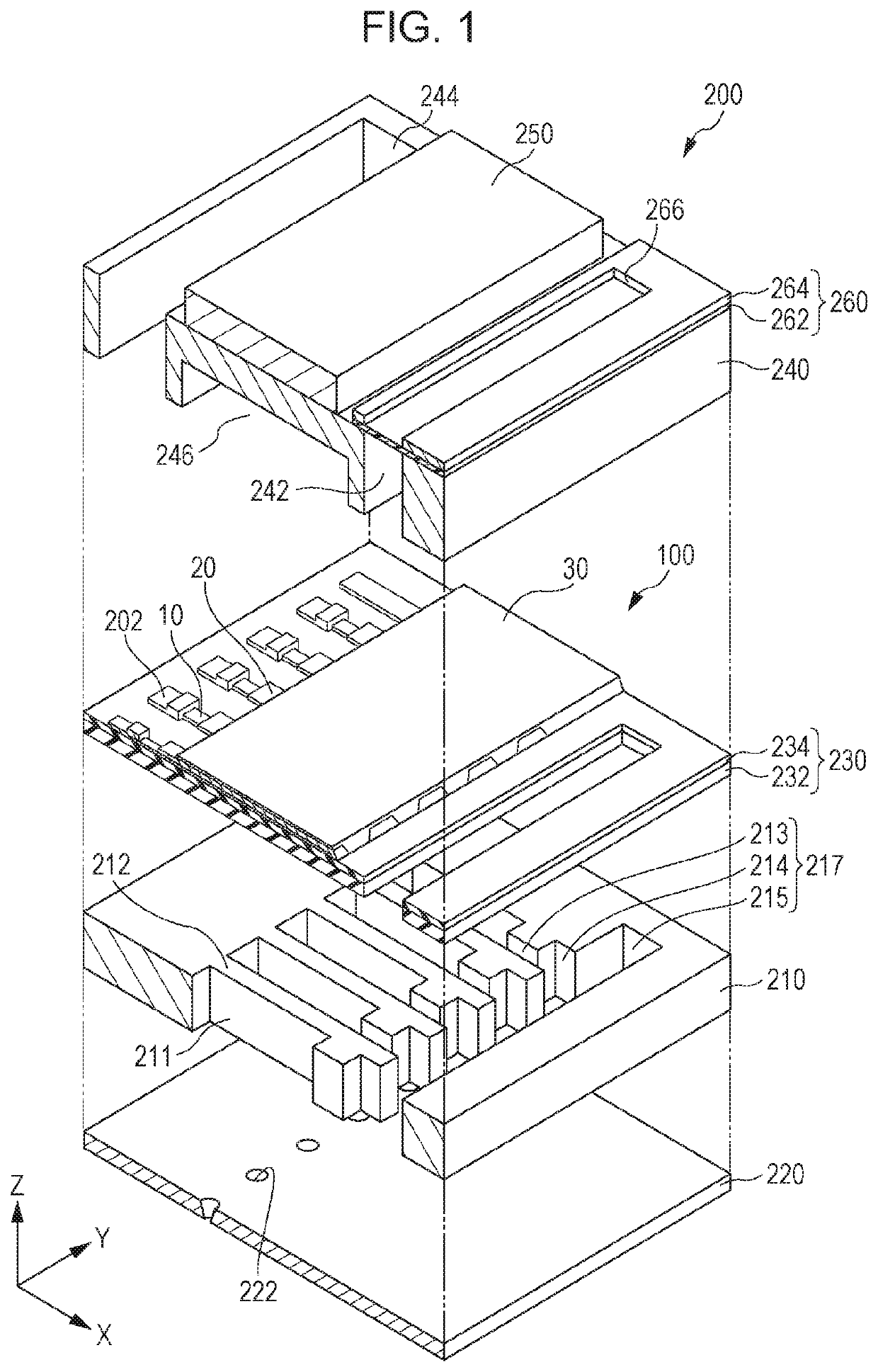
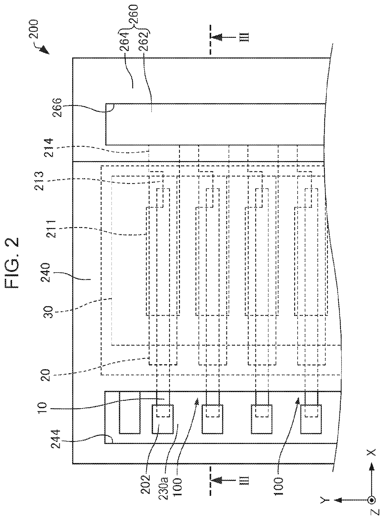
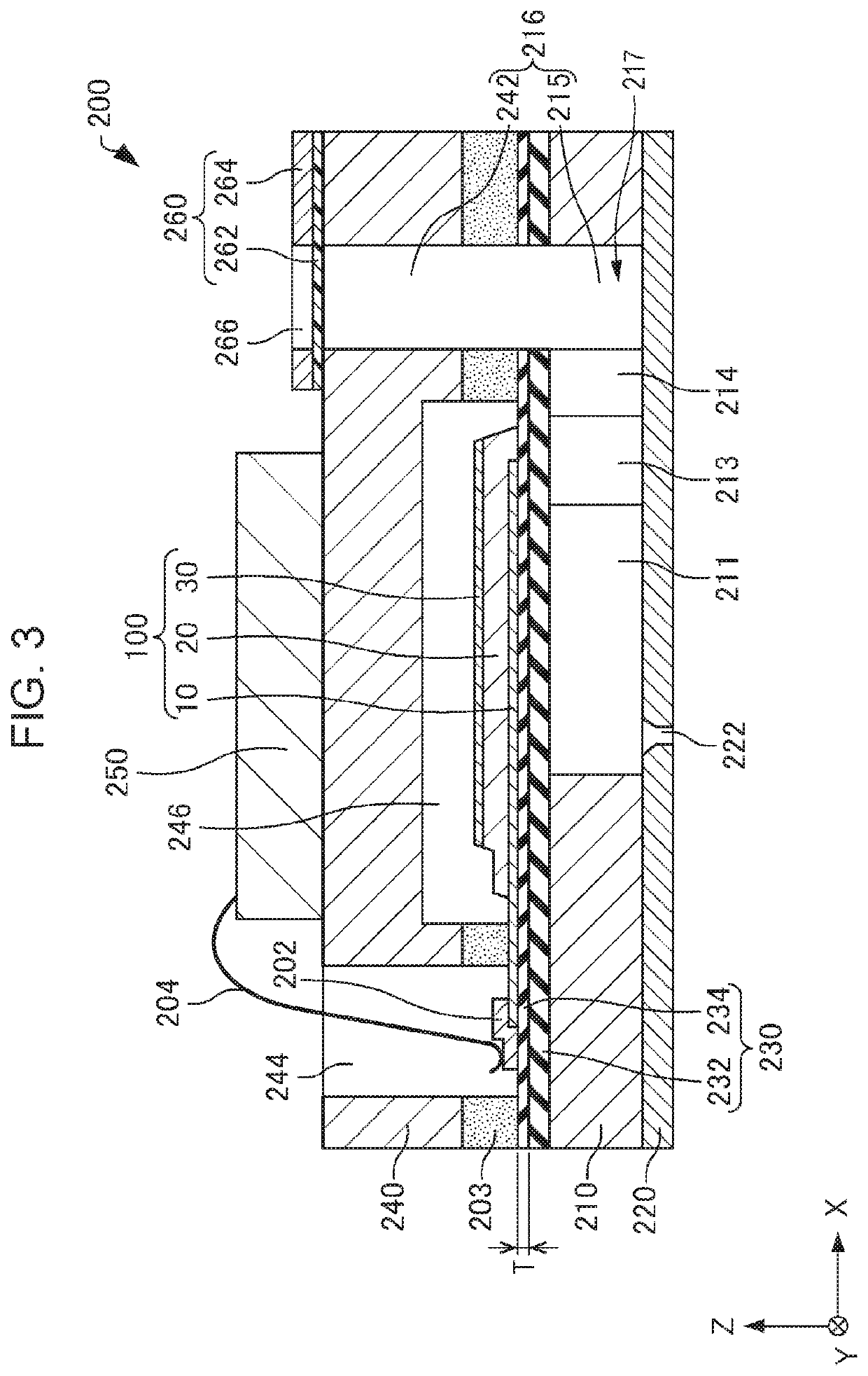
Liquid discharge head and printer

Active Publication Date: 2020-10-01
SEIKO EPSON CORP
View PDF0 Cites 0 Cited by
  • Summary
  • Abstract
  • Description
  • Claims
  • Application Information

AI Technical Summary

Benefits of technology

The present patent relates to a liquid discharge head for a printer, which uses a piezoelectric element to change the volume of a pressure chamber connected to a nozzle hole, and includes a diaphragm made of zirconium oxide with a preferred orientation. The X-ray diffraction of the diaphragm results in a difference between the position of the zirconium oxide layer and the silicon substrate of 7.5° or more and 7.7° or less. The liquid discharge head has improved printing quality and stability. The printer includes a liquid discharge head and a transport mechanism that moves the recording medium relative to the liquid discharge head. The control unit controls the liquid discharge head and the transport mechanism for efficient printing.

Problems solved by technology

As a result, cracking occurs in the diaphragm in some cases.

Method used


Image

  • Liquid discharge head and printer
  • Liquid discharge head and printer
  • Liquid discharge head and printer

Examples


example 1

4.1.1. Example 1

[0073]In Example 1, a silicon substrate was thermally oxidized to form a SiO2 layer on the surface of the silicon substrate. Subsequently, a Zr layer was formed on the SiO2 layer by sputtering at a pressure of 0.02 Pa and a substrate temperature of room temperature. As the first heat treatment, the Zr layer was then thermally oxidized at 900° C. to form a ZrO2 layer. The thickness of the ZrO2 layer was set to 400 nm. Through the above procedure, a diaphragm consisting of the SiO2 layer and the ZrO2 layer was formed.

[0074]Next, a titanium layer, a platinum layer, and an iridium layer were formed in this order on the diaphragm by sputtering and patterned into a predetermined shape to form a first electrode.

[0075]Subsequently, a piezoelectric layer was formed on the first electrode through the following procedure.

[0076]A PZT precursor solution was prepared by weighing, in a container, acetic acid and water, then weighing lead acetate, zirconium tetra-n-butoxide, titaniu...

example 2

4.1.2. Example 2

[0079]Example 2 is the same as Example 1 except for performing heat treatment at 750° C. as the second heat treatment after forming a ZrO2 layer through the first heat treatment.

example 3

4.1.3. Example 3

[0080]Example 3 is the same as Example 1 except for performing heat treatment at 850° C. as the second heat treatment after forming a ZrO2 layer through the first heat treatment.

4.1.4. Comparative Example 1

[0081]Comparative Example 1 is the same as Example 1 except for performing heat treatment at 1,000° C. as the second heat treatment after forming a ZrO2 layer through the first heat treatment.

4.1.5. Comparative Example 2

[0082]Comparative Example 2 is the same as Example 1 except for: performing heat treatment at 850° C. as the second heat treatment after forming a ZrO2 layer through the first heat treatment; and forming two ZrO2 layers by further repeating a series of steps of forming a Zr layer, thermally oxidizing the Zr layer through the first heat treatment, and performing the second heat treatment at 850° C. In Comparative Example 2, the thickness of one ZrO2 layer was 400 nm and the thickness of two ZrO2 layers was thus 800 nm.

4.2. Characteristics Evaluation

[...


PUM


Abstract

A liquid discharge head includes: a nozzle plate provided with a nozzle hole that discharges a liquid; a silicon substrate provided with a pressure chamber that is connected with the nozzle hole; a diaphragm provided on the silicon substrate; and a piezoelectric element that is provided on the diaphragm and that changes a volume of the pressure chamber, where: the diaphragm includes a zirconium oxide layer; the zirconium oxide layer has (−111) preferred orientation; and in X-ray diffraction of the diaphragm, a difference between a position of (002) peak of the zirconium oxide layer and a position of (220) peak of the silicon substrate is 13.26° or more and 13.30° or less.

Description

[0001]The present application is based on, and claims priority from JP Application Serial Number 2019-060836, filed Mar. 27, 2019, the disclosure of which is hereby incorporated by reference herein in its entirety.BACKGROUND1. Technical Field[0002]The present disclosure relates to a liquid discharge head and a printer.2. Related Art[0003]A representative example of liquid discharge heads is, for example, an ink jet-mode recording head in which a diaphragm is deformed by piezoelectric elements to pressurize ink within pressure chambers, thereby discharging ink droplets from nozzle holes. As in JP-A-2011-142153, for example, a piezoelectric element used for such an ink jet-mode recording head is formed by sandwiching, between two electrodes, a piezoelectric material that exhibits an electromechanical conversion function, such as a piezoelectric layer formed from a crystallized dielectric material.[0004]A diaphragm used in a liquid discharge head, even in the state without application ...

Claims


Application Information

Patent Timeline
IPC IPC(8): B41J2/14
CPCB41J2/14233B41J2002/14419B41J2002/14491B41J2002/14241B41J2202/03H10N30/2047H10N30/706
Inventor KOIKE, HARUNOBUAIMONO, TAKANORINAKAYAMA, MASAOTAKABE, MOTOKISUMI, KOJIITAYAMA, YASUHIRO
Owner SEIKO EPSON CORP
Features
  • Generate Ideas
  • Intellectual Property
  • Life Sciences
  • Materials
  • Tech Scout
  • Unparalleled Data Quality
  • Higher Quality Content
  • 60% Fewer Hallucinations
Learn More