
Hollow-core fiber with Anti-resonant arches and method of manufacturing thereof

a technology of anti-resonant arches and hollow core fibers, which is applied in the direction of manufacturing tools, cladded optical fibres, instruments, etc., can solve the problems of limiting the hc-pbg transmission range to the transparency of glass materials used, unable to achieve coherent reflection, and almost no light-guiding role, so as to achieve the effect of preserving the shape and uniformity of hollow arches, reducing the loss of fiber transmission, and reducing the loss of fiber

Active Publication Date: 2020-10-15
IRFLEX CORP
View PDF0 Cites 6 Cited by
  • Summary
  • Abstract
  • Description
  • Claims
  • Application Information

AI Technical Summary

Benefits of technology

The present invention is about creating better hollow-core fibers for infrared applications using special glass. The invention uses infrared soft glass with anti-resonant optical arches to minimize transmission loss. The arches are attached to the outer solid region to ensure their shape and uniformity during fabrication. The method uses three-dimensional printing to create a smooth surface and tight dimension tolerances for the extrusion die, which results in a smooth surface and very tight tolerances for the hollow-core preform. The invention offers low-loss transmission of less than 1 dB / m in the mid-to-long-infrared range.

Problems solved by technology

However, the guided light in the core strongly overlaps with the glass contour microstructure, which limits the HC-PBG transmission range to the transparency of the glass material used because of the light absorption in the glass struts.
Studies have demonstrated that most of the light confinement in the Kagome lattice fibers occurs due to anti-resonance in the core surrounding ring with little contribution due to the second ring: the remaining part of the periodic layers of holes is not effective at creating coherent reflections and has almost no light-guiding role.
However, silica cannot be used for HC-AR fiber at wavelengths >4.3 microns because the small portion of the guided light that interacts with the silica core-surround is highly absorbed and does not propagate far.
Further, the manufacture of such single-ring non-touching tube fiber with the conventional stack-and-draw technique is very challenging.
The precise stacking of the non-touching tubes in the preform is difficult to achieve and maintain up to the fiber draw.
Variations in tube thickness and spacing will inevitably change the fiber transmission performances.
However, infrared glasses are soft with low melting temperature, and the manufacturing process of HC-AR fiber with soft glass is even more challenging.
Furthermore, it would be extremely unlikely to successfully use the stack-and-draw technique with infrared soft glasses to manufacture the HC-AR fiber with non-touching tubes while controlling precisely the thickness, shape, and spacing between tubes.
The produced HC-AR fiber showed some transmission in the long-infrared window around 10 microns, but it had significant fabrication imperfections (variations in inner tubes diameter (±8%), thickness (±7%), and spacing (±34%)) that resulted in “blurring” of the transmission band and fairly high transmission loss >2.1 dB / m.
The non-touching tubes are susceptible to lateral movement during fiber fabrication, especially when pressurization is used.
The fabrication of HC-AR fiber with non-touching tubes appears to be difficult to use with soft glass while controlling precisely the thickness, shape, and spacing between tubes.
However, none of them can efficiently use infrared soft glasses to produce the desired HC-AR fiber for mid- to long-infrared light with the tight geometry tolerances (<5%) required to achieve a low transmission loss of <1 dB / m.

Method used


Image

  • Hollow-core fiber with Anti-resonant arches and method of manufacturing thereof
  • Hollow-core fiber with Anti-resonant arches and method of manufacturing thereof
  • Hollow-core fiber with Anti-resonant arches and method of manufacturing thereof

Examples


example 1

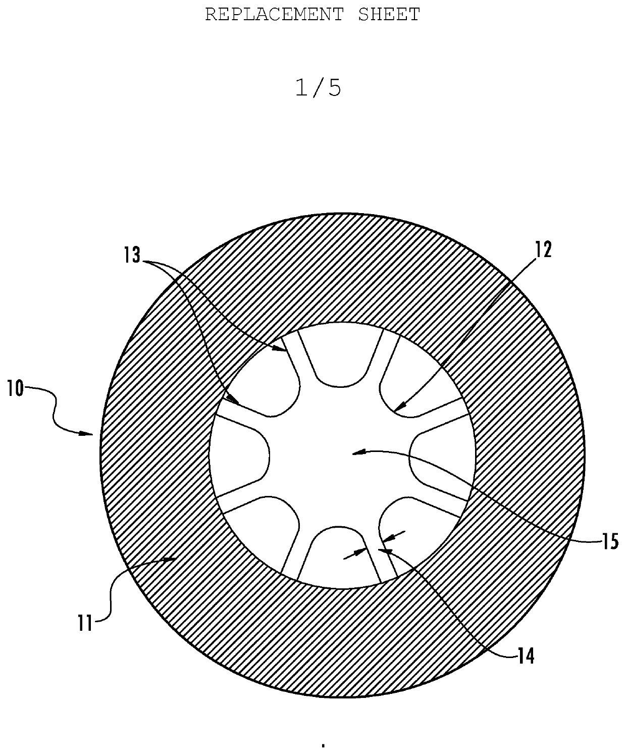
[0026]The hollow-core preform with anti-resonant arches was extruded with the extrusion die showed in FIGS. 2A and 2B. The extruded preform was made of infrared chalcogenide glass, more specifically As2S3 composition. The As2S3 glass is transparent in the infrared up to 6.5 microns. The As2S3 glass billet was 25.1 mm in diameter, 70 mm long, and was inserted in the stainless steel sleeve for extrusion.

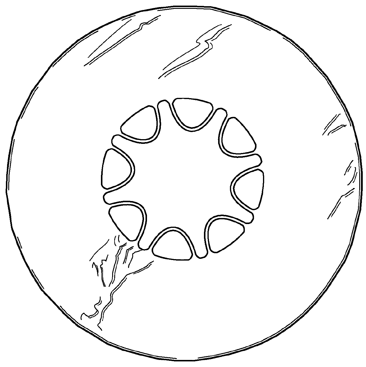
[0027]Referring to FIG. 3, a preform was extruded at a draw speed of 0.48 mm / min. The sleeve temperature was 380° C. and the piston speed was fixed at 0.15 mm / min, which resulted in a load of 35-40 kg on the piston. The extruded preform diameter was 16 mm and the length was about 150 mm. As shown in FIG. 3, the arches preserved the shape of the die shown in FIGS. 2A and 2B. The height of the arches was 1.3 mm and the wall thickness was 0.18 mm, which was thinner than the gap of 0.449 mm in the die. The hollow core diameter was approximately 4.8 mm. The hollow-core preform dimensions we...

example 2

[0028]Example 2 relates to a design of the hollow-core fiber with 8 anti-resonant arches for the transmission of CO2 laser light at 10.6 microns. The fiber parameters used for the simulations are: As2S3 glass, a hollow core diameter of 0.185 mm, an anti-resonant arch wall thickness of 3.7 microns, and a gap between the arches of 21.5 microns. FIG. 4 illustrates the calculated intensity profile of the fundamental mode at 10.6 microns. The intensity is clearly reflected by the anti-resonant arches and barely penetrates within the gaps. FIG. 5 illustrates the calculated spectral loss of the fundamental mode of the hollow-core fiber with anti-resonant arches. Two transmission windows are illustrated, one centered around 10 microns wavelength (1st order resonance) and the other centered around 6.5 microns (2nd order resonance). The calculated transmission loss of the fundamental mode at 10.6 microns was 0.138 dB / m. The calculated transmission loss of the hollow-core fiber with anti-reson...


PUM

PropertyMeasurementUnit
Wavelengthaaaaaaaaaa
Optical gainaaaaaaaaaa

Abstract

A hollow-core fiber with a single layer of robust anti-resonant optical arches is disclosed, which is designed and made of infrared soft glass and allows the transmission of mid- to long-infrared wavelengths (1-15 microns). Each curved arch is solidly attached at two locations on the outer solid region surface and together the arches define the core diameter. The thickness and spacing between the arches are selected to minimize the fiber transmission loss <1 dB / m at wavelengths in the mid- to long-infrared where the infrared soft glass has high absorption >30 dB / m. A hollow-core preform with anti-resonant arches is made by extrusion of infrared soft glasses through a die specifically designed to produce the hollow-core fiber with anti-resonant arches.

Description

BACKGROUND OF THE INVENTIONField of the Invention[0001]Embodiments of the present invention relate generally to the design and precise fabrication of a hollow-core anti-resonant fiber, and more particularly to a hollow-core fiber made from an extruded soft glass preform that utilizes a single layer of robust reflecting optical arches for transmission of mid- to long-infrared light. The guidance mechanism and design of this fiber allow the low-loss transmission of wavelengths of light which falls within the high absorption spectrum of the confining material.Description of Related Art[0002]The hollow-core photonic band gap (HC-PBG) fiber is a special photonic crystal fiber design, which guides light in the air-core surrounded by a periodic 2-dimensional array of small holes in the cladding (see, for example, J. C. Knight, J. Broeng, T. A. Birks, and P. S. J. Russell, “Photonic band gap guidance in optical fibers,” Science 282(5393), 1476-1478 (1998)). In the HC-PBG fiber the light is ...

Claims


Application Information

Patent Timeline
IPC IPC(8): G02B6/02C03B37/012C03B37/022
CPCC03B37/01274G02B6/02328C03B2203/22C03B2203/16C03B37/022C03B2201/82C03B2201/86C03B2203/14C03B2203/42
Inventor CHENARD, FRANCOISALVAREZ, OSCAS
Owner IRFLEX CORP
Learn More