

Thermal Management System for High Power Electrical Equipment
a technology of electrical equipment and management system, which is applied in the direction of battery/fuel cell control arrangement, secondary cell servicing/maintenance, cell components, etc., can solve the problems of high cost of replacement of degraded lithium-ion batteries, limited service life, and fast depletion of lithium-ion, so as to reduce energy consumption and prolong the operating time of electrical equipment , the effect of lowering the temperature of the battery
- Summary
- Abstract
- Description
- Claims
- Application Information
AI Technical Summary
Benefits of technology
Problems solved by technology
Method used
Image

Examples
first embodiment
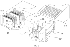
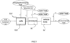
[0036]FIG. 2 shows an exploded view of a thermal management system for high power electrical equipment according to the present invention, wherein the electrical equipment, which can be illustrated as an electric vehicle, which is furnished with a battery pack, which generally contains multiple cells accommodated in an enclosure. FIG. 3 shows various heat sources that can affect the performance of the battery pack. As shown, the heat sources include sunlight, motor heat, and heat produced from battery charging / discharging, wherein radiant heat of sunlight can be introduced to the battery enclosure 90′ via the vehicle body 94′, especially when the vehicle is running on a summer day. During charging / discharging process, the temperature of the battery cells 920′ may increase. Additionally, the battery enclosure 90′ and the battery cells 920′ are subjected to heat from the external environment and the vehicle while running, which may further cause the temperature of the battery cells to...
second embodiment
[0046]In the second embodiment, only the large temperature adjustment unit 12″ is installed with thermal dissipation means (not shown) for cooling the coolant flowing through the small and large temperature adjustment units 10′, 12′ that are selectively connected through a selection device 14″. As such, the large temperature adjustment unit 12′ involves the internal thermal conduit 161″ corresponding to the battery cells 920″ (which are grouped into at least one module 92″) as well as the external thermal conduit 162″ corresponding to the battery enclosure 90″, whereas the small temperature adjustment unit 10″ involves only the internal thermal conduit 161″, which is associated with the battery cells 920″, and can be selectively connected with the large temperature adjustment unit 12″ through the section valve 14″. The selection device 14″ can be operated to enable the small temperature adjustment unit 10″ or the large temperature adjustment unit 12″. Therefore, when the capacity of...
third embodiment
[0050]FIGS. 7 and 8 show the present invention, wherein an independent charging station 96′″ incorporating a thermal management system is shown. The thermal management system comprises temperature adjustment means, sensing means, and a microcontroller 3″. As electric vehicles are becoming more and more popular, even in wild area, charging stations are built along a road at intervals. For this kind of charging stations, an electrical connection by cables from remote sites may spend a huge amount of money. It is preferred that the charging stations are energized by wind or solar power and provided with battery modules 92′″ to store the energy. As such, the rest area and service area near the charging station may rely on the battery modules 92′″ as an energy source. However, during charging / discharging process, the battery cells 920′″ can produce a lot of heat. Furthermore, there may be great variations in environmental temperature. These factors may adversely affect the operation of t...
PUM
 Abstract
Description
Claims
Application Information