Lithium ion battery using high surface area nanotubes
Active Publication Date: 2021-09-30
MOLECULAR REBAR DESIGN LLC
View PDF2 Cites 0 Cited by
Summary
Abstract
Description
Claims
Application Information
AI Technical Summary
This helps you quickly interpret patents by identifying the three key elements:
Problems solved by technology
Method used
Benefits of technology
Benefits of technology
The patent text explains how energy storage devices such as batteries and capacitors use a binder, electrolyte, and separator film to improve their performance. The text also highlights the challenges faced by lithium ion batteries, which have poor electrical conductivity and stability, leading to poor cycling ability. The text suggests that the issue is related to the swelling and deswelling of the battery materials during charging and discharging, which causes separation of particles and increased electrical resistance. This can lead to excessive heat generation and potentially dangerous chemical reactions. The patent seeks to address the challenges faced by lithium ion batteries and improve their stability and performance.
Problems solved by technology
The salts for the cathode materials in lithium ion batteries are generally known to have poor electrical conductivity and poor electrochemical stability which results in poor cycling (charge / discharge) ability.
The high internal resistance of the batteries, particularly in large arrays of lithium ion batteries such as used in electric vehicles, can result in excessive heat generation leading to runaway chemical reactions and fires due to the organic liquid electrolyte.
These lithium primary batteries have excellent storage lifetimes, but suffer from only being able to provide low current and the capacity is about one tenth of what is theoretically possible.
These high amounts of carbon black needed for improved electrical conductivity, or reduced impedance of the battery, diminish the capacity per unit volume of the battery as less manganese dioxide can be employed per unit volume of the positive paste mix.
The carbon particle anodes tend to have poor mechanical strength leading to fracture under conditions of vibration and mechanical shock.
Materials such as lithium manganese oxide for cathodes and silicon particles for anodes exhibit much lower practical specific capacity than theoretically available.
Impurities, such as non-lithium salts, iron, and manganese to name a few, with the binder can also be highly deleterious to battery performance.
Commercially available carbon nanotubes such as NC7000™ (Nanocyl) or Graphistrength® (Arkema) can contain as much as ten percent or more by weight of residual metal catalysts and are not considered advantageous for batteries at these levels of impurity.
During the burning off of the polymer and cooling the lines can crack due to shrinkage forces and so increase impedance.
The low ionic conductivities of polymer and inorganic solid electrolytes are presently a limitation to their general use in energy storage and collection devices.
One of the most serious drawbacks of the present DSSCs technology is the use of liquid and corrosive electrolytes which strongly limit their commercial development.
Replacement of the presently used electrolytes is desirable, but candidate electrolytes have poor ion transport.
However, utilization of carbon nanotubes in these applications has been hampered due to the general inability to reliably produce higher-surface area carbon nanotubes and the ability to disperse carbon nanotubes in a matrix.
Method used
Image
Click on the blue label to locate the original text in one second.
Reading with bidirectional positioning of images and text.
Examples
example 1
Tuball™ (OCSiAl)
[0095]Thirty-five grams of >64% nitric acid is heated to 95 degrees C. To the acid, 15 grams of as-received, single-walled carbon nanotubes (Tuball™) are added. The as-received tubes have the morphology of tightly bundled tree-trunks. The mixture of acid and carbon nanotubes are mixed while the solution is kept at about 95 degrees for 5 hours and is labeled “oSWCNT-82-2”. At the end of the reaction period, the oSWCNT 82-2 are filtered to remove the acid and washed with reverse osmosis (RO) water to pH of 3-4. The resulting CNTs were oxidized to about 3.6% and contained about 4.4% metal residue.
[0096]Variations on this process were also conducted using slightly differing parameters as shown below in Table 1:
[0097]Samples oxidized by MAO process: e.g. 35 g HNO3 (65%) / 15 g Tuball™, 95° C. oxidation.
[0098]23.33 g HNO3 (65%)+10.01 g CNT. T=95° C. Initial big plume of NOx at addition of CNT.
[0108]1200 g×0.15%=1.8 g dry equiv.=6.64 g wetcake. Used 6.65 g wetcake.
[0109]Check viscosity through Rotor Stator R / S as shown below.
T (min)T (° C.)Comments023531Clear liquid droplets on plastic coveringvessel opening. Not viscous941Clear liquid droplets on plasticcovering vessel opening. Notviscous+6.62 g wetcake1550Viscous mixture. Proceed to shearing
Place in Freezer for ˜1.5 hr.
[0110]Shearing
Pass #T (° C.)Comments1251500 psi because noticed some large particlespresent when cleaning the rotor stator236342Place in freezer 45 minutes → 15° C.4315376457511 hr freezer → 25° C.839Sample for optical microscopy
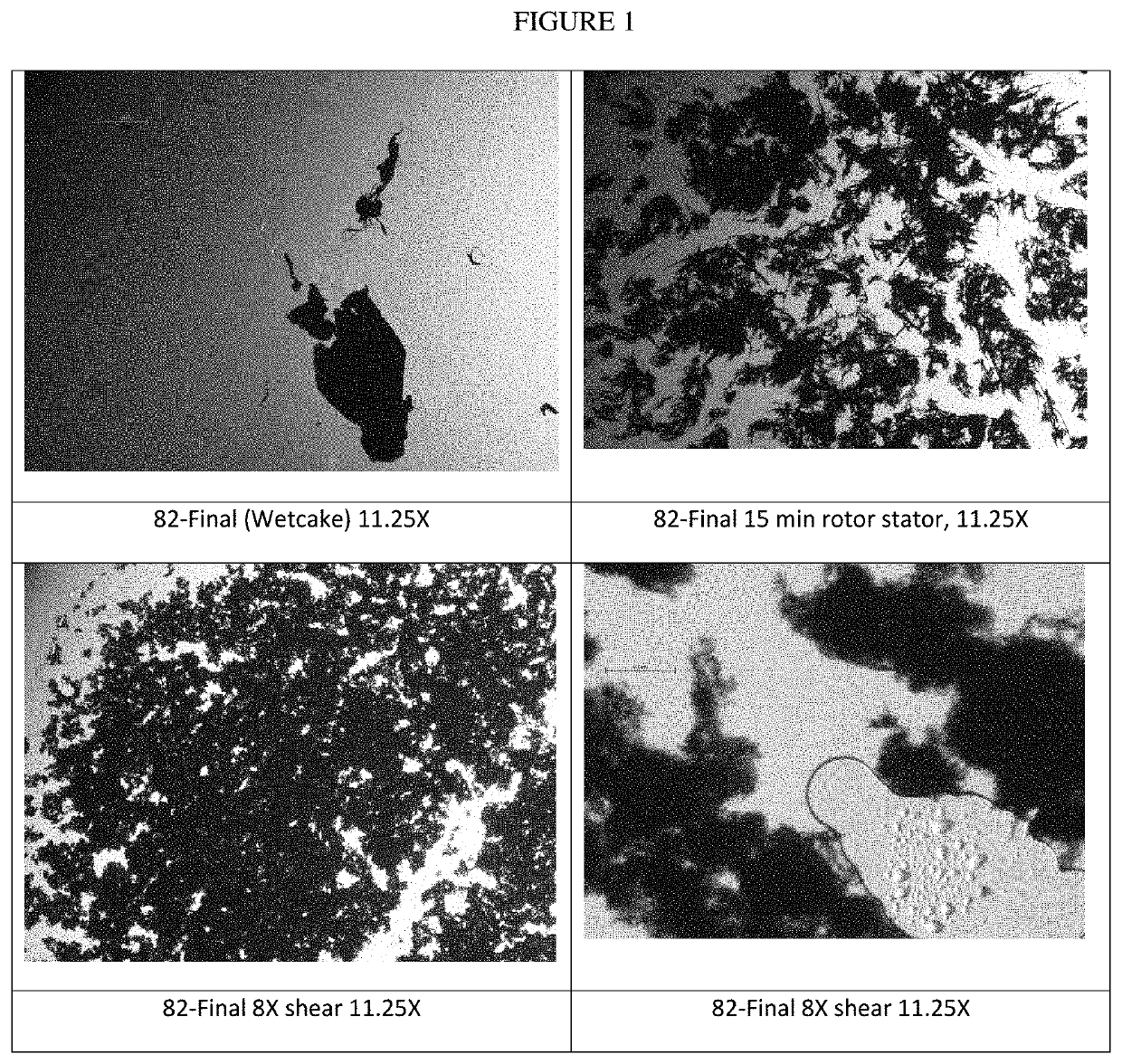
[0111]Sample name 180417-MF-1A (0.26% solids), 180417-MF-1B (0.22% solids) ˜19 g.
[0112]Optical Microscopy, shown in FIG. 1, shows a progression from wetcake to rotor she...
PUM
Abstract
High-surface area carbon nanotubes having targeted, or selective, oxidation levels and / or content on the interior and exterior of the tube walls are claimed. Such carbon nanotubes can have little to no inner tube surface oxidation, or differing amounts and / or types of oxidation between the tubes' inner and outer surfaces. Additionally, such high-surface area carbon nanotubes may have greater lengths and diameters, creating useful mechanical, electrical, and thermal properties.
Description
FIELD OF INVENTION[0001]The present invention is directed to an improved energy storage device comprising novel carbon nanotube compositions having increased surface area, targeted oxidation levels and / or content, and formulations thereof.BACKGROUND AND SUMMARY OF THE INVENTION[0002]Many energy storage devices like batteries, capacitors and photovoltaics can utilize a binder and / or an electrolyte and separator film to provide enhanced performances in mechanical stabilization, improved electrical conduction of the powder used in cathodes or electrodes and ion transport in the electro- or photoactive material and electrolyte.[0003]Lithiumion batteries are used extensively for portable electronic equipment and batteries such as lithiumion and lead-acid are increasingly being used to provide electrical back-up for wind and solar energy. The salts for the cathode materials in lithium ion batteries are generally known to have poor electrical conductivity and poor electrochemical stabili...
Claims
Application Information
Patent Timeline
Application Date:The date an application was filed.
Publication Date:The date a patent or application was officially published.
First Publication Date:The earliest publication date of a patent with the same application number.
Issue Date:Publication date of the patent grant document.
PCT Entry Date:The Entry date of PCT National Phase.
Estimated Expiry Date:The statutory expiry date of a patent right according to the Patent Law, and it is the longest term of protection that the patent right can achieve without the termination of the patent right due to other reasons(Term extension factor has been taken into account ).
Invalid Date:Actual expiry date is based on effective date or publication date of legal transaction data of invalid patent.

