Eureka AIR delivers breakthrough ideas for toughest innovation challenges, trusted by R&D personnel around the world.

Method to remove explosive and toxic gases and clean metal surfaces in hydrocarbon equipment

Pending Publication Date: 2021-11-04
PRAXAIR TECH INC
View PDF2 Cites 0 Cited by
  • Summary
  • Abstract
  • Description
  • Claims
  • Application Information

AI Technical Summary

Benefits of technology

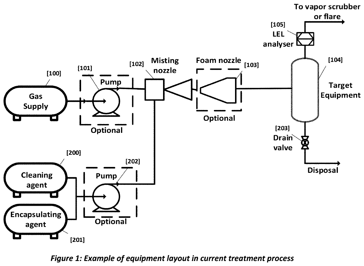
The patent describes a system for cleaning equipment, such as heavy oil storage tanks. The system uses different cleaning chemistries that work at different temperatures. The patent also provides a description of the typical layout of the equipment and a commercial application of the invention. The technical effects of the patent are to provide a more effective and versatile system for cleaning equipment, especially heavy oil storage tanks.

Problems solved by technology

This maintenance may be planned or unplanned.
They require an extensive amount of planning and scheduling of labor, services and materials.
Often, a turnaround can cause parts of the plant or the entire facility to shut down.
This partial or complete shutdown involves temporary reduction in production and significant associated cost impact and potential loss in revenue.
Some gases are also toxic at very minimal concentrations (e.g., H2S) and needs removal to other safe limits.
Some equipment (e.g., small pumps, low pressure storage tanks) may be left open to atmosphere to vent hydrocarbon vapors especially if the facility is not located near a city where odor problems may be of concern.
This renders atmospheric venting ineffective and cost prohibitive not to mention, very environmentally unfriendly.
Furthermore, if the equipment is in the critical path during a turnaround, atmospheric venting might be more expensive that other options accounting for time value of money.
Another disadvantage is that by atmospheric venting, there is no cleaning of any metal surfaces, only removal of LELs or toxic hydrocarbon gases.
Given nitrogen dilutes energy content, at times the FGRU becomes the limiting factor and increases time to complete LEL freeing of equipment.
In the heavy oil industry in Canada, process equipment can contain 3-5 feet of sludge in tanks which causes complications with purging.
This makes estimating the total nitrogen required to LEL free a vessel difficult and causes safety issues since the atmosphere might not be inert a time period later.
Handling and processing of petroleum and petrochemical products almost always results in metallic surfaces coated with residue.
This is a significant problem especially in heat exchangers, since petroleum products tend to deposit on metal surfaces causing heat exchange coefficient decay, reduced heat transfer area and significant cost impact.
The patent does not anticipate the need for removal of noxious gases from equipment, only cleaning of the metal surfaces.
Recirculation methods involve a significant amount of chemical waste along with expensive disposal issues.

Method used


Image

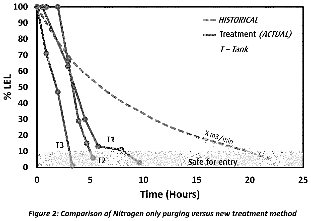
  • Method to remove explosive and toxic gases and clean metal surfaces in hydrocarbon equipment
  • Method to remove explosive and toxic gases and clean metal surfaces in hydrocarbon equipment

Examples


example 4

[0047]Metal coupons were coated with 1 gram of Canadian bitumen and a comparative analyses of solvency strength was tested by spraying 10 ml of highly aromatic and natural solvents. Solvency strength was analyzed by quantification of the residues dislodged and from the coupon as a percentage of the total initial weight. Results are tabulated in Table 2. Additional tests were conducted to quantify the influence of elevated temperature Table 3, clearly indicating increased solubility of the organic residue at higher temperature. Although there were 14 solvents tested, any C5-C45 hydrocarbon may be used as the cleaning agent.

TABLE 2Solubilization of Bitumen using organic solvents% Bit. RemovedNo.Chemical(ambient)1Friction reducing agent2Heavy reformate39.53Toluene / Xylene mix414Reformed Naphtha385Xylene736Toluene527Gas oil8Distillates (I)26.49Distillates (II)10Heavy aromatic5naphtha11Terpene6012Turpentine1313Paint Thinner26.114Methyl Ester−10.6

TABLE 3Effect of Temperature on solubility ...


PUM


Abstract

The present invention relates to a method of rapidly decontaminating and making safe for entry, hydrocarbon contaminated equipment by sequencing a cleaning mist or foam, an encapsulating mist or foam and a dry carrier gas.

Description

RELATED APPLICATIONS[0001]This application claims the benefit of U.S. Provisional Application Ser. No. 63 / 018,131, filed on Apr. 30, 2020, which is incorporated herein by reference.FIELD OF INVENTION[0002]The present invention relates to a method of rapidly decontaminating and making safe for entry, hydrocarbon contaminated equipment by sequencing a cleaning mist or foam, an encapsulating mist or foam and a dry carrier gas. This enables a significant (e.g., greater than 50%) time reduction for decontamination compared to alternate methods. Target process equipment includes but is not limited to oil storage vessels, piping conduits, process vessels, heat exchangers, distillation columns, compressors, connectors, rotating equipment and pumping stations wherein the storage and processing of crude oil and its derivatives results in progressive contamination of metal surfaces of equipment and presence of toxic vapors that are a health threat to site personnel. Equipment must undergo sche...

Claims


Application Information

Patent Timeline
IPC IPC(8): C11D11/00C11D3/00C11D3/30C11D3/20C11D3/18B08B3/00B08B3/08
CPCC11D11/0041C11D3/0094C11D3/30B08B3/08C11D3/185B08B3/003C11D3/2093B08B9/0327B08B9/0328B08B9/08C11D2111/20
Inventor ZACHARIAH, ASHLEYKELLY, RICHARD M.ST. JAMES, MICHAELGULAYETS, JOSEPH E.
Owner PRAXAIR TECH INC
Why Eureka
Eureka Blog
Learn More