Electrode having NANO structure at tip

a technology of nanostructure and electrode, which is applied in the direction of instruments, specific use of bioreactors/fermenters, biomass after-treatment, etc., can solve the problems of measuring devices, and achieve the effects of suppressing cell damage, and reducing the number of electrodes

Pending Publication Date: 2021-11-18
ION CHAT RES CORP
View PDF0 Cites 2 Cited by
  • Summary
  • Abstract
  • Description
  • Claims
  • Application Information

AI Technical Summary

Benefits of technology

[0044]In the present invention, no magnetic force is required for the conductive nanoparticles to penetrate the cell membrane and for the electrodes to be self-fixed on the cell surface, and the intracellular potential and the potential change can be measured more easily.
[0045]Furthermore, in the present invention, compared to the previously developed method, damage to cells can be suppressed and fluctuations in intracellular potential can be observed while allowing cells to survive in a normal state for a long period of time. Furthermore, the design is compact including the measuring device, and it can be used as a “Clip on ground” by using a capacitive potential measuring device type electrode. In addition, by using a donut-shaped electrode with a ring-shaped magnet, MagEle can be fixed and self-supporting without a magnetic iron plate. Light can be directly projected onto the test cells using the central hole to stimulate light and observe light signals.
[0046]FIG. 1 illustrates conceptual diagram of a metho...

Problems solved by technology

It is a method that enables measuring intracellular potential over a long period of time; however, a magnetic field is required not only to allow the con...

Method used


Image

  • Electrode having NANO structure at tip
  • Electrode having NANO structure at tip
  • Electrode having NANO structure at tip

Examples


examples

[0161]Examples will be shown below, and the present invention will be more specifically described; however, the present invention is not limited thereto.

[0162]Other terms and concepts in the present invention are based on the meanings of terms commonly used in the art, and various techniques used to carry out the present invention particularly including techniques whose sources are clearly stated. Except for this, those skilled in the art can easily and surely carry out the procedure based on known documents and the like.

[0163]In addition, various analyses were performed according to the methods described in the analytical instruments or reagents used, the instruction manuals for the kits, catalogs, and the like. The technical documents, patent gazettes, and patent application specifications cited in the present specification shall be referred to in the description contents of the present invention.

(Reference Example 1) Measurement of Intracellular Potential in HEK Cells that Stably...

reference example 2

(Reference Example 2) Method of Measuring by Applying the Principle of a Charge Amplifier

(Reference 2-1) Preliminary Experiment for Applying the Principle of Charge Amplifier

[0183]This experiment is an experiment to show that the measurement system is effective in measuring the bioelectric potential by combining the charge amplifier with nanoparticles introduced into the cell (FIG. 12).

[0184]Circuit A adds a rectangular current pulse (20 ms, 120 pA) to a model cell (cell equivalent circuit: a circuit in which a 500 MΩ resistor and a 33 pF capacitor are connected in parallel) to the current-clamp mode patch-clamp amplifier Axoptch 200A used for recording. The potential change through the equivalent circuit was measured (FIG. 8 circuit A).

[0185]Following that, a conductive glass that serves as a sensor for the charge amplifier was connected between the equivalent circuit and the negative input of the amplifier. In order to make this conductive glass act as a capacitor, an aluminum foi...

example 6

(Example 6) Construction of “Capacitive Potential Measuring Device” with Holder

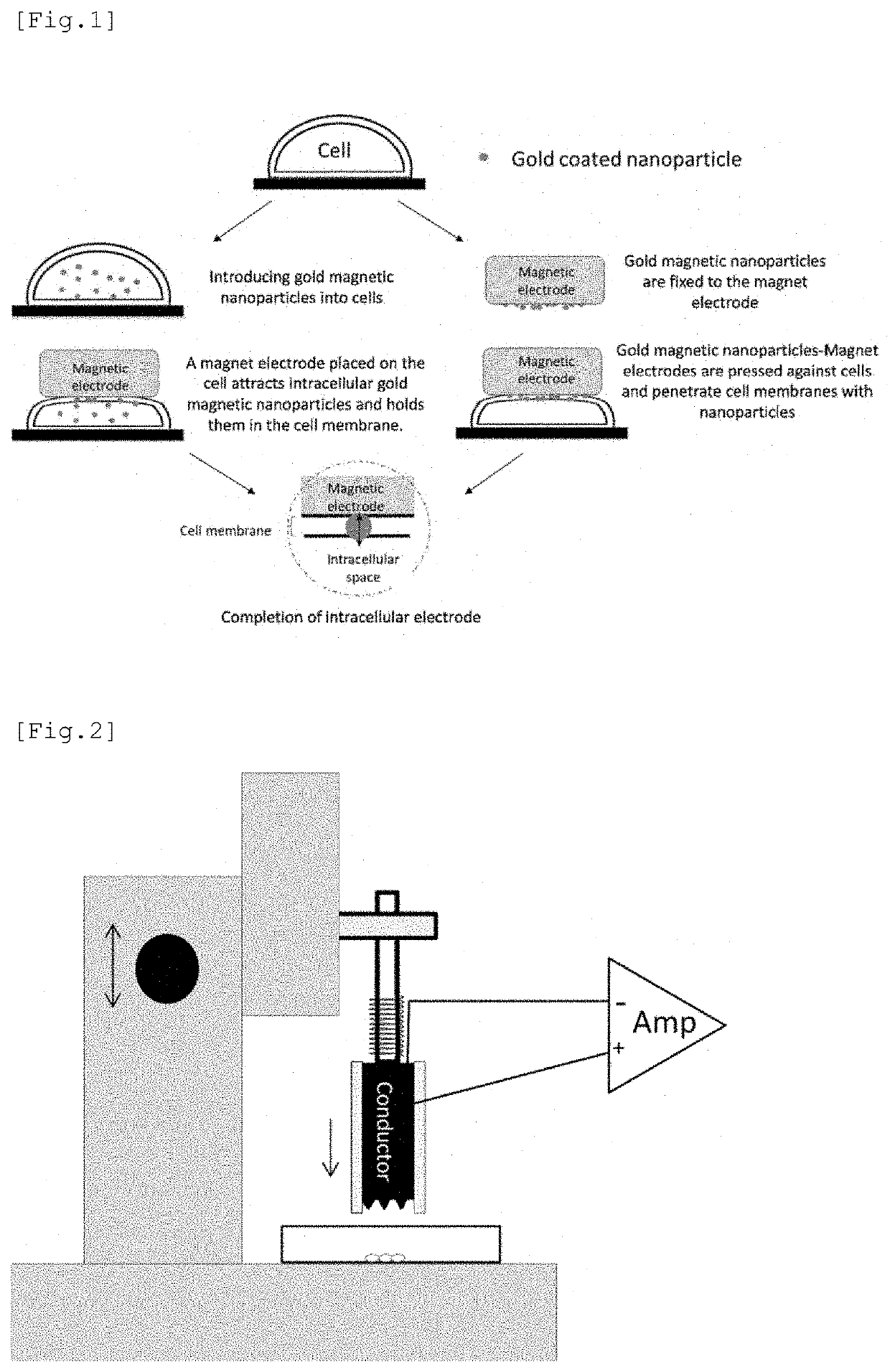
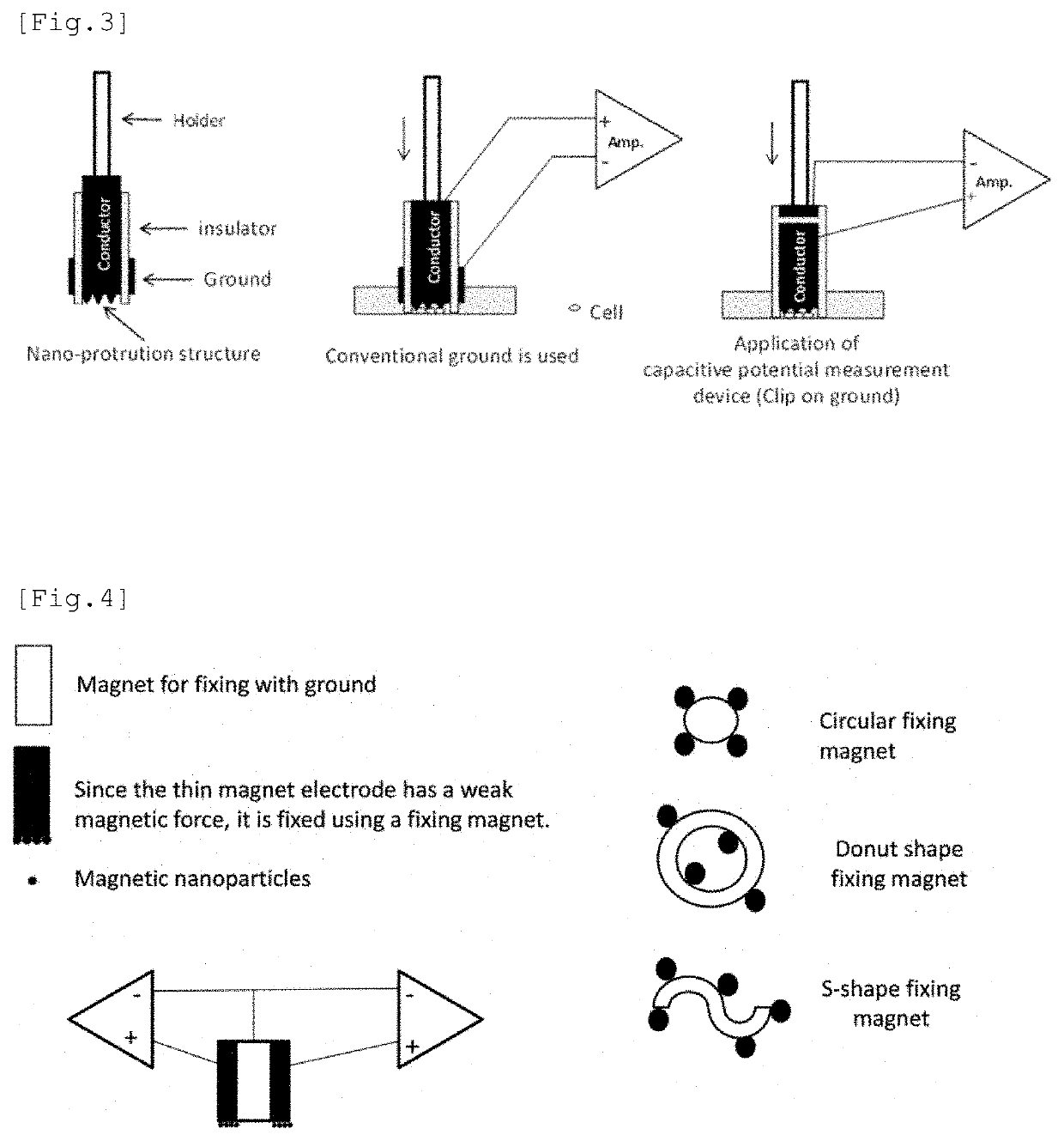
[0246]By applying the “capacitive potential measuring device method” (Japanese Patent Application No. 2018-87689) developed by the present inventors, a compact “capacitive potential measuring device” with a holder (FIG. 3, right) was constructed. Here, as shown in (FIG. 3, right), the ground (reference electrode) of the “capacitive potential measuring device” with a holder is integrated with the electrode by connecting it to the negative side of the measuring instrument or the ground terminal (See the description of “Clip on ground” in 4.4-4 above). This “capacitive potential measuring device” with a holder has a conductive nano (particle) structure at the tip that penetrates the cell membrane. By detecting the change in electric potential inside the cell and charging the conductor (magnet electrode, etc.) with which the conductive nano (particle) structure is in contact. The intracellular potential chang...


PUM


Abstract

The purpose of the present invention is to provide a method which is designed to form an intracellular recording electrode for a cell by a simple operation which is less invasive to the cell and does not need a magnetic force, and with which the short-term or long-term intracellular potential can be accurately measured. More specifically, provided is a method comprising: securing, to a manipulator or the like, a holder provided on a conductor having a conductive nano structure at a tip; making the tip nano structure part penetrate a cell membrane while adjusting the amount of pressure applied to the target cell, thereby forming an intracellular recording electrode independently secured above the cell; and measuring the intracellular potential. The conductive nano structure at the tip and the conductor main body do not have to be magnetic but may be stuck together by magnetic force or may be formed as one body. When the cell membrane potential of a target cell cultured in a typical culture vessel is recorded, by forming the conductor main body of a magnetic electrode (MagEle) and independently securing same using a ring-shaped magnet that is provided on the lower surface of the culture vessel and that secures a light projection path or a light observation path through the center thereof, measurement of the intracellular potential of the target cell and fluorescent observation of changes in intracellular potential due to a light stimulus or intracellular calcium dynamics can be performed simultaneously.

Description

TECHNICAL FIELD[0001]The present invention relates to an electrode having a nanostructure at the tip, a method of measuring an intracellular potential or a change in potential using the electrode, and a method of controlling the intracellular potential.BACKGROUND ART[0002]All cells have different ionic compositions inside and outside the cell, and the intracellular potential (membrane potential) is maintained by a transporter (i.e., sodium pump) that keeps the difference in ion distribution and the difference in ionic composition. In the resting state, the membrane potential is stable (resting membrane potential); however, when the ion channels on the cell membrane surface are activated and the ion channels are opened, ions are released or flow in at once through the ion channels due to the difference in ion concentration inside and outside the cell membrane. This causes the electric potential of the entire cell changes where depolarization or hyperpolarization occurs, and consequen...

Claims


Application Information

Patent Timeline
IPC IPC(8): C12M1/34G01N33/50
CPCC12M1/34C12Q1/02G01N33/5061G01N33/5088C12M35/02C12M1/42
Inventor SAITO, MITSUYOSHI
Owner ION CHAT RES CORP
Why Eureka
Try Eureka