Resistance spot welding method and method for producing resistance spot welded joint

Pending Publication Date: 2021-11-25
JFE STEEL CORP
View PDF0 Cites 0 Cited by
  • Summary
  • Abstract
  • Description
  • Claims
  • Application Information

AI Technical Summary

Benefits of technology

[0024]According to aspects of the present invention, when a resistance spot welding method is carried out on a sheet combination of a plurality of overlapping steel sheets including at least one high-strength steel sheet, by reducing segregation at a nugget edge in a resistance spot weld zone of the high-strength steel s

Problems solved by technology

However, when the technique of Patent Literature 1 or 2 is applied to a steel sheet containing, as a steel sheet component, Mn: 2.5 to 10.0% by mass (hereinafter, referred to as the “medium Mn steel sheet”), the following problems exist.
However, in short-time cooling and postheating as in the technique described in Patent Literature 1 or 2, it is not possible to ensure complete martensitic transformation or produce a tempered martensite structure.
Therefore, the effect of im

Method used


Image

  • Resistance spot welding method and method for producing resistance spot welded joint

Examples


examples

[0089]The effects and advantages of aspects of the present invention will be described below on the basis of examples. It is to be noted that the present invention is not limited to the examples described below.

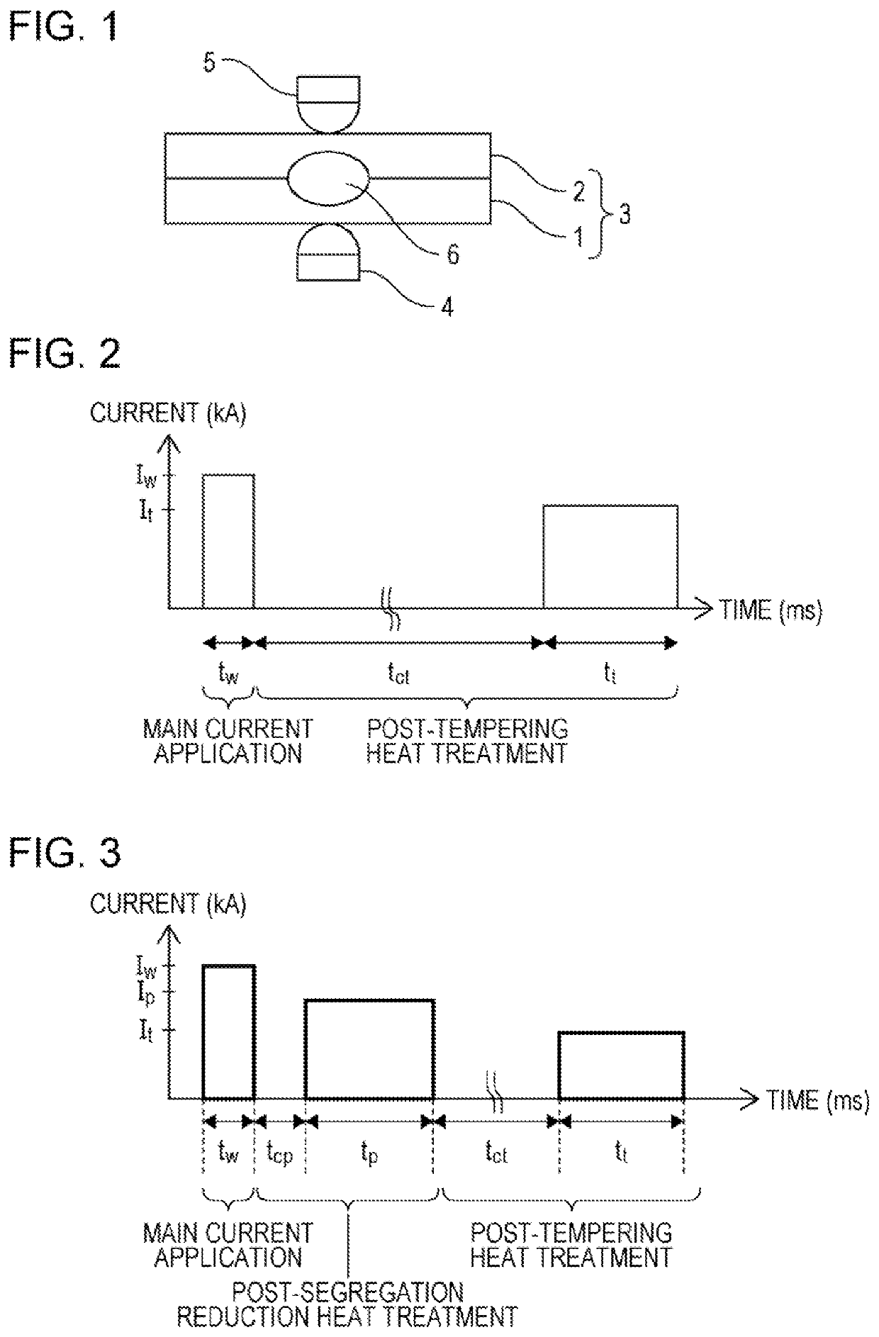
[0090]In examples of the present invention, on a sheet combination 3 of overlapping two steel sheets (a lower steel sheet 1 and an upper steel sheet 2) as shown in FIG. 1, resistance spot welding was performed using a resistance welder of a servomotor pressing type attached to a C gun and having a direct-current power source. A nugget 6 with a required size was formed, and a resistance spot welded joint was produced.

[0091]As specimens, 780 MPa to 1,180 MPa class high-strength steel sheets (steel sheets A to F) with a thickness of 1.2 mm were used. The size of the specimens was as follows: a long side of 150 mm and a short side of 50 mm. As the steel sheets A to F, steel sheets having compositions shown in Table 1-1 were used. Hereinafter, “%”, which shows the composition of t...


PUM

PropertyMeasurementUnit
Electric chargeaaaaaaaaaa
Tensile strengthaaaaaaaaaa
Timeaaaaaaaaaa

Abstract

The present invention provides a resistance spot welding method. A resistance spot welding method according to the present invention in which a sheet combination of two or more overlapping steel sheets is sandwiched between a pair of electrodes and joined together by applying current while applying pressure, the method including a main current application step in which current application is performed with a current Iw (kA), and subsequently, a post-tempering heat treatment step in which after cooling is performed for a cooling time tct (ms) shown in formula (1) below, current application is performed with a current It (kA) shown in formula (2) below for a current application time tt (ms) shown in formula (3) below: 800≤tct . . . formula (1), 0.5×Iw≤It≤Iw . . . formula (2), and 500≤tt . . . formula (3).

Description

CROSS REFERENCE TO RELATED APPLICATIONS[0001]This is the U.S. National Phase application of PCT / JP2019 / 004069, filed Feb. 5, 2019, which claims priority to Japanese Patent Application No. 2018-021591, filed Feb. 9, 2018, the disclosures of these applications being incorporated herein by reference in their entireties for all purposes.FIELD OF THE INVENTION[0002]The present invention relates to a resistance spot welding method and a method for producing a resistance spot welded joint.BACKGROUND OF THE INVENTION[0003]In recent years, various types of high-strength steel sheets (high-tensile strength steel sheets) have been increasingly applied to automobile bodies from the viewpoint of reducing body weight to improve fuel efficiency and securing crashworthiness. Resistance spot welding (hereinafter, may also be referred to as “spot welding”) is used primarily for joining members formed of such high-strength steel sheets, such as automobile structural members in automobile assembly line...

Claims


Application Information

Patent Timeline
IPC IPC(8): B23K11/11B23K11/16B23K11/24C21D9/50C22C38/54C22C38/50C22C38/48C22C38/46C22C38/44C22C38/42C22C38/06C21D6/00C22C38/00C22C38/02C22C38/04
CPCB23K11/115B23K2101/006B23K11/24C21D9/50C22C38/54C22C38/50C22C38/48C22C38/46C22C38/44C22C38/42C22C38/06C21D6/004C22C38/002C22C38/02C22C38/04B23K11/16B23K2101/18B23K2103/04B23K31/00
Inventor ENDO, REIKOMATSUSHITA, MUNEOTANIGUCHI, KOICHIMATSUDA, HIROSHIIKEDA, RINSEI
Owner JFE STEEL CORP
Why Eureka
Try Eureka