Tbm-mounted virtual reconstruction system and method for surrounding rock structure of tunnel

a virtual reconstruction and tunnel technology, applied in the field of geotechnical engineering, can solve the problems of affecting work efficiency, large workload, long time, etc., and achieve the effects of reducing labor, increasing construction efficiency, and increasing safety

Active Publication Date: 2021-11-25
SHANDONG UNIV
View PDF0 Cites 2 Cited by
  • Summary
  • Abstract
  • Description
  • Claims
  • Application Information

AI Technical Summary

Benefits of technology

[0029]The present disclosure is mounted on a TBM, and does not affect TBM construction during a working process. The present disclosure can continuously obtain data from the TBM in the TBM tunneling process, collect surrounding rock image data at different positions according to system settings, and remotely control working state data of the system, thereby realizing automatic work. Manual surveillance for a long time is not required, thereby reducing labor and leading to higher construction efficiency, more safety, and more convenience.
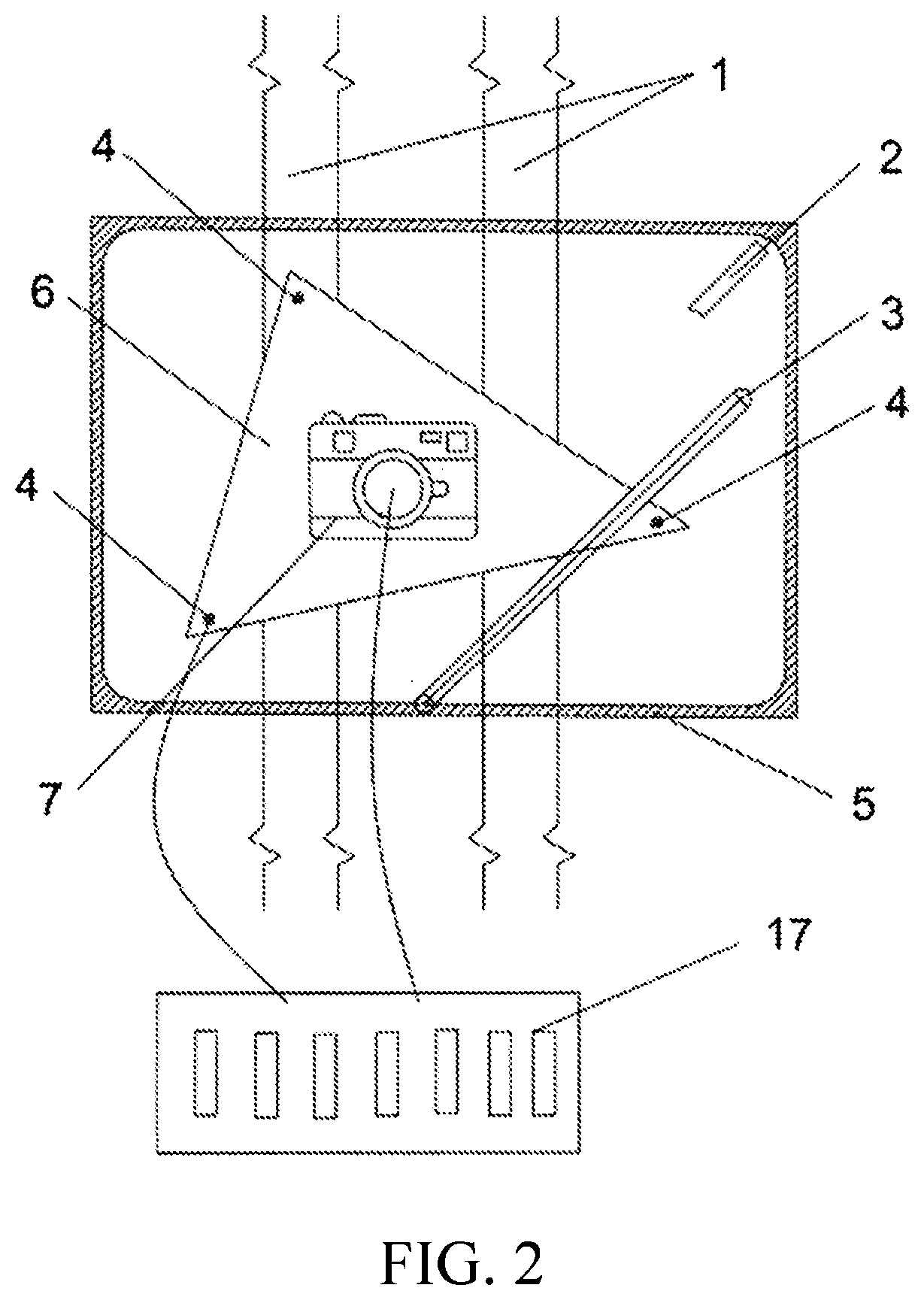
[0030]The present disclosure obtains a panoramic image of the surrounding rock by using a steel track and a protective box, thereby reducing a quantity of cameras, reducing construction costs, and reducing occupation of tunnel space. In addition, the protective box can prevent the camera from being damaged by falling rocks and polluted by dust during use of the camera, and a determining and processing method for automatic cleaning is used to ensure that tempered glass on a side of the protective box is transparent when the camera is used, to ensure that pictures captured by the camera are clear and reliable.
[0031]The present disclosure integrates functions such as collection of information about tunnel surrounding rock, digital

Problems solved by technology

Sketching work is greatly dependent on work experience of the sketcher, and has a large workload.
Especially for a long and large tunnel, it takes a long time to enter

Method used


Image

  • Tbm-mounted virtual reconstruction system and method for surrounding rock structure of tunnel
  • Tbm-mounted virtual reconstruction system and method for surrounding rock structure of tunnel
  • Tbm-mounted virtual reconstruction system and method for surrounding rock structure of tunnel

Examples

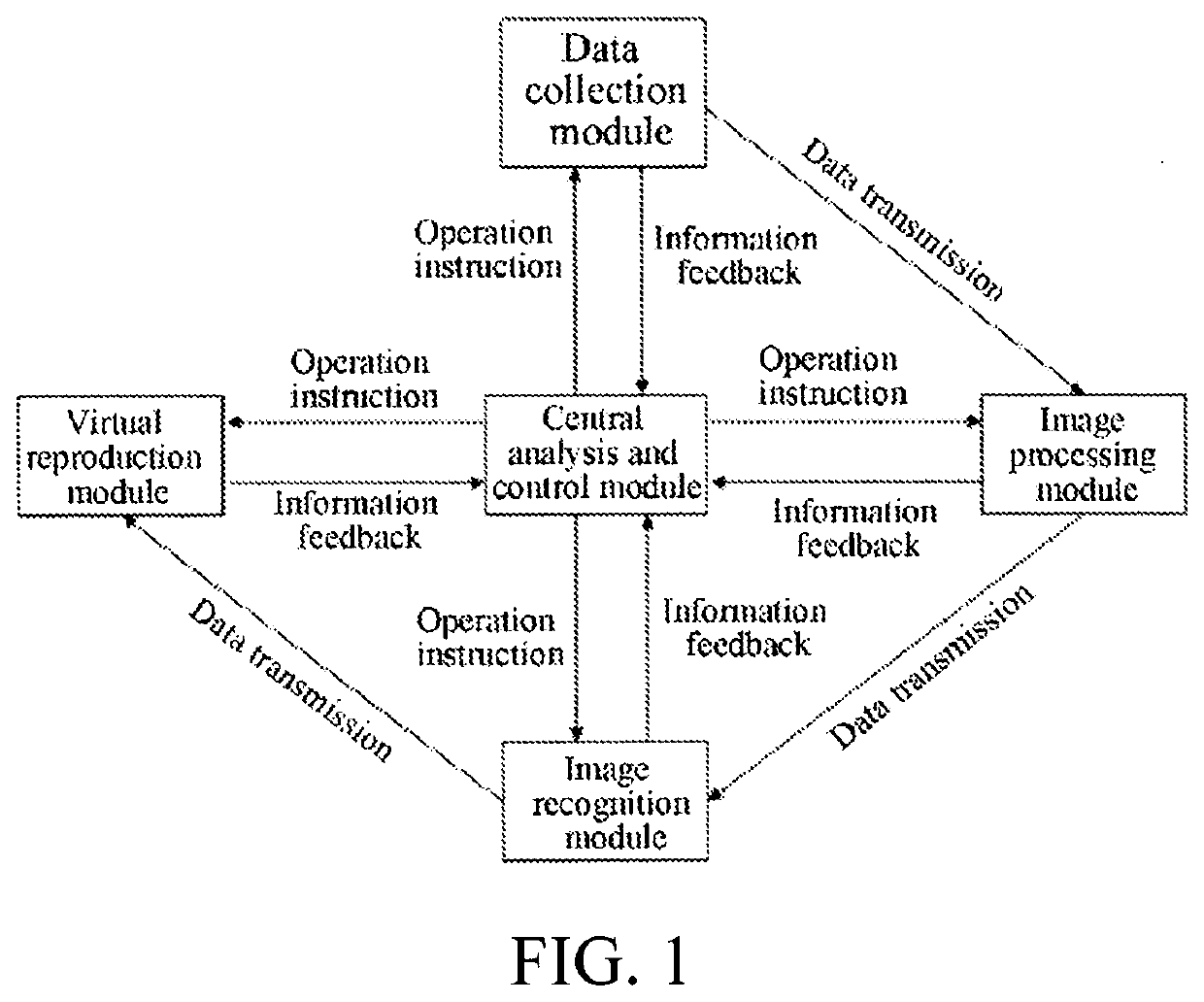

Embodiment Construction

[0043]The present disclosure is further described below with reference to the accompanying drawings and embodiments.

[0044]It should be noted that, the following detailed descriptions are all exemplary, and are intended to provide further descriptions of the present disclosure. Unless otherwise specified, all technical and scientific terms used herein have the same meanings as those usually understood by a person of ordinary skill in the art to which the present disclosure belongs.

[0045]It should be noted that the terms used herein are merely used for describing specific implementations, and are not intended to limit exemplary implementations of the present disclosure. For example, unless otherwise specified in the context, singular forms are also intended to include plural forms. In addition, it should be further understood that, when the terms “comprise” and / or “include” are used in this specification, it indicates that there is a feature, a step, an operation, a device, a componen...


PUM


Abstract

A TBM-mounted virtual reconstruction system and method for a tunnel surrounding rock structure, the method including: obtaining image information of surrounding rock; receiving the image information of the surrounding rock; transforming and splicing pictures taken at different angles, to form a complete image reflecting the surrounding rock; recognizing and describing a surrounding rock feature of the complete image, and transmitting the annotated image to a virtual reconstruction module; displaying the complete image with a description of the surrounding rock feature by using a virtual reality device, to reflect surrounding rock situations at different angles/different positions. This has the advantages of high equipment automation, not prolonging the construction time, not requiring the sketcher to enter the tunnel, precise surrounding rock feature parameters, and supporting remote control.

Description

BACKGROUNDTechnical Field[0001]The present disclosure belongs to the field of geotechnical engineering, and relates to a TBM-mounted virtual reconstruction system and method for a surrounding rock structure of tunnel.Related Art[0002]The description in this section merely provides background information related to the present disclosure and does not necessarily constitute the prior art.[0003]Monitoring surrounding rock of tunnel is an indispensable part of tunnel construction and an important means for ensuring safety of tunnel engineering. A geological sketch of surrounding rock structure of tunnel can precisely reflect properties of the tunnel surrounding rock structure, accurately quantify some important parameters of the surrounding rock structure of tunnel, and guide construction personnel to make an advance geological prediction for the tunnel. The geological sketch may be compared with the advance geological prediction to verify accuracy of the advance geological prediction.[...

Claims


Application Information

Patent Timeline
IPC IPC(8): G06T17/05G06T7/00
CPCG06T17/05G06T7/97G06T7/0002G06T7/0004G06T7/70G06T3/4038G06T19/00G06T19/006B08B1/002B08B3/02B08B13/00G06T2207/30132G06T2207/20084G06T2200/08G06T2210/04G06V20/52H04N23/52H04N23/51G06T7/33G06T2207/20081
Inventor LI, SHUCAISHI, HENGXU, ZHENHAOLIN, PENGLIU, FUMINCHEN, SIWANG, XIAOTE
Owner SHANDONG UNIV
Why Eureka
Try Eureka