System and method for preventing thermal induced failures in vertical cavity surface emitting laser (VCSEL) array

a technology of laser array and vertical cavity surface, which is applied in the direction of semiconductor lasers, laser details, electrical equipment, etc., can solve the problems of reducing power output, vcsel array power dissipation and related thermal effects under continuous-wave (cw) operation, and vcsel arrays also exhibit large thermal impedances, so as to prevent thermal destruction and catastrophic failure of vcsel array, overcome overheating, and improve the effect o

Pending Publication Date: 2021-12-02
SHENZHEN RAYSEES AI TECH CO LTD
View PDF0 Cites 0 Cited by
  • Summary
  • Abstract
  • Description
  • Claims
  • Application Information

AI Technical Summary

Benefits of technology

The present invention helps to prevent overheating and failure of VCSEL arrays by identifying areas with higher temperature after operation. These areas are then separately controlled to reduce currents or power, preventing damage to the VCSELs.

Problems solved by technology

One performance limitation of VCSEL arrays is the power dissipation and the related thermal effects under continuous-wave (CW) operation.
Self-heating in a VCSEL is caused by the excessive heat and the accumulation of heat inside the laser cavity.
VCSELs also exhibit large thermal impedances because they are small and the DBRs have poor thermal conductivity.
The resultant thermal problems include overheating of a VCSEL which reduces power output, causes higher thresholds, and changes wavelength of the VCSEL output.
The problems become more prominent in VCSEL arrays.
In particular, overheating of the central area of a two-dimensional VCSEL array, which becomes hotter than areas surrounding it after a period of operation, may cause thermal destruction and catastrophic failure of the device.
Thermal destruction of a VCSEL may start from a pre-existing defect.
Once a defect occurs in the active area, intense nonradiative recombination results in a localized hot spot which causes the defect to spread rapidly.
Growth of defects reduces the active area and thereby increases the current density, which speeds up the spread of defects further.
Thus thermal runaway may occur and the device may experience catastrophic failure.
In some cases, defects spread so rapidly that a VCSEL device may fail in hours after the defects enter the active area.
In the worst-case scenario, thermal runaway may occur in the encircled area and VCSEL 100 may be destructed by catastrophic failure.
But this design requires that the central area of a VCSEL array has lower density than areas surrounding it, which is not practical when equal or even higher VCSEL density is needed in the area.

Method used


Image

  • System and method for preventing thermal induced failures in vertical cavity surface emitting laser (VCSEL) array
  • System and method for preventing thermal induced failures in vertical cavity surface emitting laser (VCSEL) array
  • System and method for preventing thermal induced failures in vertical cavity surface emitting laser (VCSEL) array

Examples


Embodiment Construction

Mode for Invention

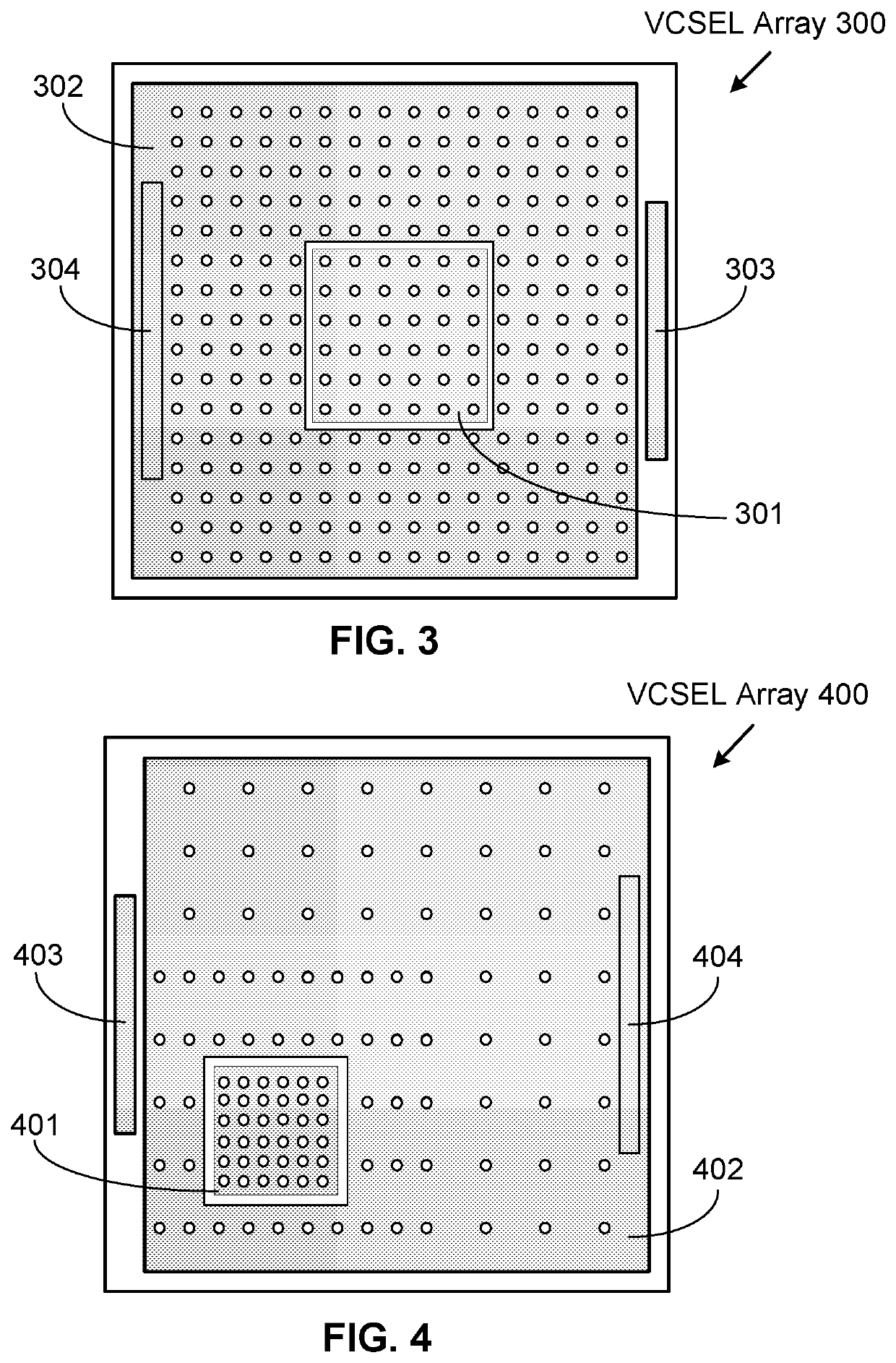
[0020]FIG. 3 illustrates an exemplary VCSEL array 300 in a top view, according to one embodiment of the present invention. Array 300 comprises VCSELs arranged in a matrix, a regular pattern. The array is divided into two areas, a central area covered by a metal layer portion 301, and a surrounding area covered by a metal layer portion 302. The central area includes the center of the array. The two metal layer portions, as two common anode terminals for the VCSELs in the two areas, are electrically insulated from each other. They are electrically connected to VCSELs beneath them through corresponding vias. The metal layer portions may be formed from two metal layers deposited in sequence and separated by an insulation layer (e.g. Silicon Nitride) or formed from one metal layer. A bonding pad 303 is electrically connected to metal layer portion 301 and arranged for wire bonding. A region 304 of metal layer portion 304 is the other bonding pad, which is also arranged ...


PUM

PropertyMeasurementUnit
temperatureaaaaaaaaaa
areaaaaaaaaaaa
electrical currentsaaaaaaaaaa

Abstract

The present invention discloses a VCSEL array that is divided into at least a first and a second area. The first area covers the center of the array and is surrounded by the second area. The first area would experience higher temperature than the second area after the VCSELs in both areas are turned on for a given time period. VCSELs in the first area are electrically connected to a first metal layer portion. VCSELs in the second area are electrically connected to a second metal layer portion. The first and second metal layer portions are electrically insulated from each other.

Description

TECHNICAL FIELD[0001]This invention generally relates to Vertical Cavity Surface Emitting Laser (VCSEL) array and specifically to system and method for preventing thermal induced failures in VCSEL arrays.BACKGROUND ART[0002]VCSELs are a type of semiconductor laser which emits an output laser beam perpendicular to the top planer surface of a VCSEL wafer. They are fabricated using well-known wafer processing and testing techniques. A larger number of VCSELs can be made on a wafer to form a one dimensional or two-dimensional VCSEL array. VCSEL arrays have many uses, including applications in three-dimensional (3D) sensing. 3D sensing has become a critical technology in navigation of autonomous vehicles, augmented reality (AR), virtual reality (VR), and facial identification.[0003]One performance limitation of VCSEL arrays is the power dissipation and the related thermal effects under continuous-wave (CW) operation. Self-heating in a VCSEL is caused by the excessive heat and the accumul...

Claims


Application Information

Patent Timeline
Patent Type & Authority Applications(United States)
IPC IPC(8): H01S5/42H01S5/042
CPCH01S5/423H01S5/0428H01S5/06825H01S5/06233H01S5/04256H01S5/06216
Inventor WANG, YANGHE, YONGXIANGLANKA, SIVAKANG, DONGSEOK
Owner SHENZHEN RAYSEES AI TECH CO LTD
Why Eureka
Try Eureka