Ureteral Catheter Structure

a catheter and ureteral technology, applied in the field of in vivo catheter structures in medical appliances, can solve the problems of poor controllability and operation, poor easy damage, etc., and achieve the effect of better bending performance of the bending tube, better bending performance of the front section, and more stab operation

Pending Publication Date: 2021-12-16
STSIVITA MEDIKAL TECH KO LTD
View PDF0 Cites 0 Cited by
  • Summary
  • Abstract
  • Description
  • Claims
  • Application Information

AI Technical Summary

Benefits of technology

[0028]1. The multi-section structure provides a multi-section bending gradient, the bending performance of the bending tube is better, and the bending tube can be bent earlier than the stepped braided tube, hence the bending performance of the front sections is better, and the detection can be conducted more stably;
[0029]2. In the multi-section structure, the traction wire are not easy to swing because of the inner fasteners, the sealing performance is improved because of a hierarchical arrangement of the structures, and good waterproof performance is ensured.

Problems solved by technology

The flexible ureteroscope can eliminate blind areas in visual fields and operations, but has a soft body, is poor in controllability and difficult to operate, requires a long-term training before practicing with it, and is expensive and easy to damage.
However, in actual production and processing, the hardness of the rigid ureteroscope is uniform as the material of the whole rigid ureteroscope is substantively the same, and when the ureteroscope at the tail end is bent, the ureteroscope at the front end is easily bent or wound, as a result, the detection position of the tail end of the ureteroscope may produce more movement, which affects the use and detection effects.

Method used


Image

  • Ureteral Catheter Structure
  • Ureteral Catheter Structure
  • Ureteral Catheter Structure

Examples


Embodiment Construction

[0061]The present disclosure will now be described in further detail with reference to the accompanying drawings.

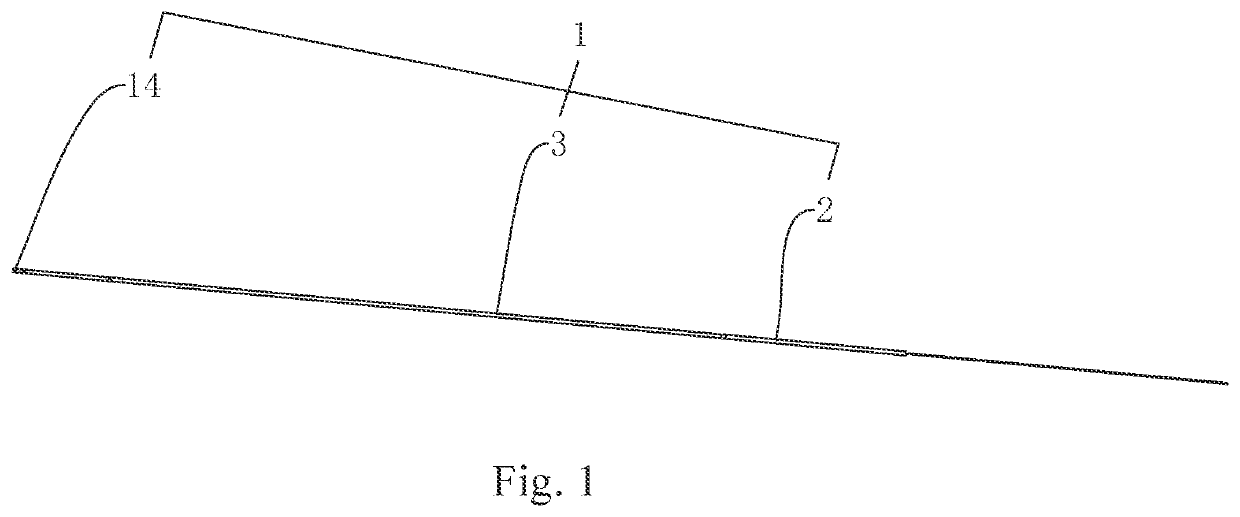
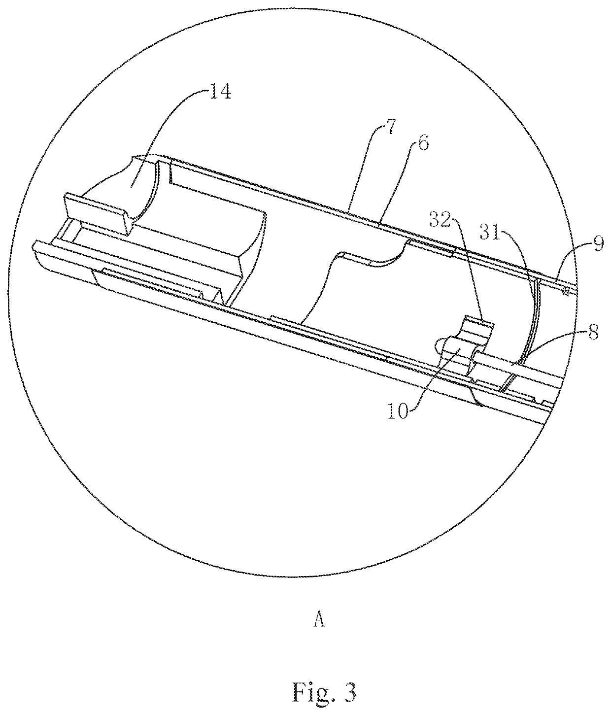
[0062]Embodiment 1: referring to FIG. 1, which discloses a ureteral catheter structure including a catheter body 1, wherein the catheter body 1 includes a stepped braided tube 2, a bending tube 3, and a plastic catheter tip 14.

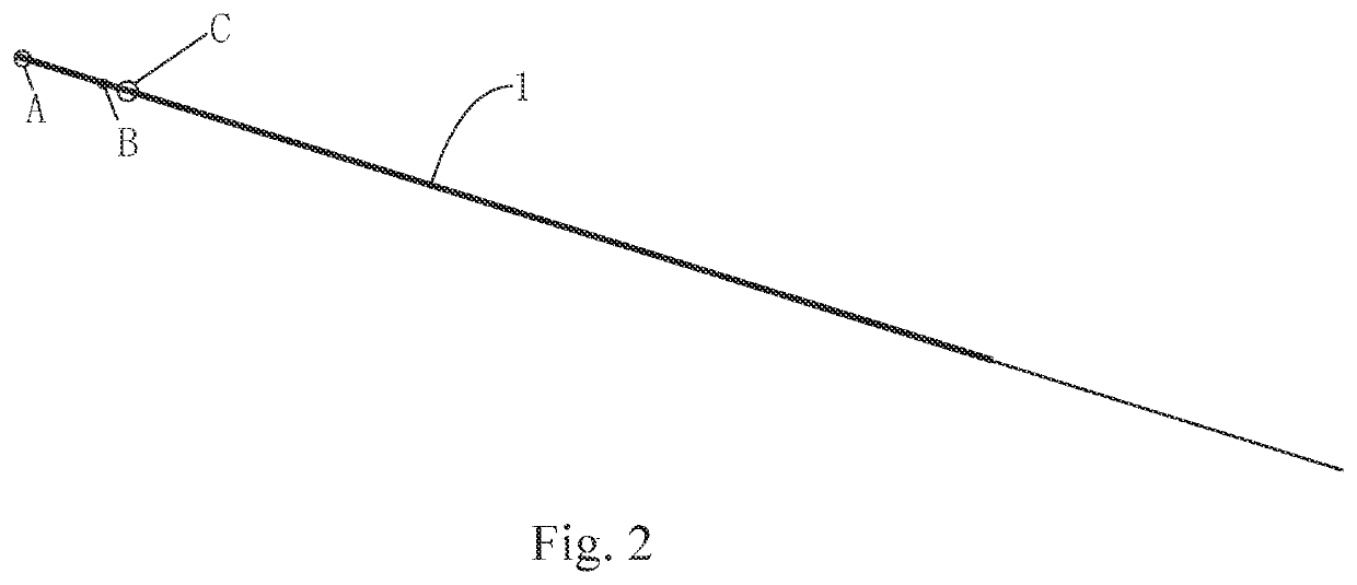
[0063]Referring to FIGS. 2 and 5, the stepped braided tube 2 may be made of a nickel-titanium alloy material, the stepped braided tube 2 is spliced with the bending tube 3, a splice between the stepped braided tube 2 and the bending tube 3 is covered by a first stainless steel outer tube 4, the first stainless steel outer tube 4 is covered by a first PET heat-shrinkable film 5 externally, and the first PET heat-shrinkable film 5 can support and connect these components after heat-shrinkable coating.

[0064]The stepped braided tube 2 is provided with an inner lining tube body 21 to enable an outer wall of the stepped braided tube 2 to form a stepped sh...


PUM

PropertyMeasurementUnit
centra angleaaaaaaaaaa
heat-shrinkableaaaaaaaaaa
lengthaaaaaaaaaa

Abstract

A ureteral catheter structure, comprising a catheter body (1). The catheter body (1) comprises a stepped braided tube (2), a bending tube (3), and a plastic catheter tip (14) which are spliced with each other. A first stainless steel outer tube (4) supports and connects the stepped braided tube (2) and the bending tube (3) at a splice therebetween, and a first PET heat-shrinkable film (5) is coated on the first stainless steel outer tube (4). A second stainless steel outer tube (6) supports and connects the bending tube (3) and the plastic catheter tip (14) at a position therebetween, and a second PET heat-shrinkable film (7) is coated on the second stainless steel outer tube (6). A traction wire (8) is provided within the catheter body (1), an end of the traction wire (8) being fixed on the bending tube (3), while the other end passing through the stepped braided tube (2). A heat-shrinkable sleeve (9) is provided outside the bending tube (3). An end of the ureteral catheter may be independently bent in multiple sections, thereby achieving a good detection effect, and solving the technical problem of instability when an end of the ureteral catheter is deflected.

Description

FIELD OF THE PRESENT DISCLOSURE[0001]The present disclosure relates to the technical field of in vivo catheter structures in medical appliances, and more particularly, to a ureteral catheter structure.BACKGROUND OF THE PRESENT DISCLOSURE[0002]A ureteroscope is an endoscope for diagnosing and treating diseases in the upper urinary tract by means of special instruments, with only a minimal incision into the human body, which significantly reduces the damage to tissues, and therefore promotes the recovery of the body, shortens the treatment, and improves the curative effect. In this sense, it represents major progress in the endoscope technology, and its clinic application reforms the traditional concept that it is difficult to perform direct observation and examination at ureter, renal pelvis, renal calyces etc., and an invasive surgery is necessary for upper urinary tract diseases. The current ureteroscope in clinic includes two types, namely, rigid ureteroscopes and flexible uretero...

Claims


Application Information

Patent Timeline
Patent Type & Authority Applications(United States)
IPC IPC(8): A61M25/00A61L29/08A61L29/02A61L29/04
CPCA61M25/0053A61L29/085A61L29/02A61M2025/0059A61L29/041A61M2210/1078A61M25/0045A61M25/0043A61M25/005A61L29/10A61B1/0051A61B1/307C08L67/02
Inventor ZHANG, YI
Owner STSIVITA MEDIKAL TECH KO LTD
Why Eureka
Try Eureka