Multi-arm robot used for tunnel lining inspection and defect diagnosis in operation period

a multi-arm robot and tunnel lining technology, applied in the field of tunnel lining inspection, can solve the problems of reducing the life of the tunnel, reducing the performance of the tunnel lining structure, and hiding structural defects, and achieves the effects of improving the stability of the robot, reducing the risk of accidents, and high flexibility

Pending Publication Date: 2021-12-16
SHANDONG UNIV
View PDF0 Cites 15 Cited by
  • Summary
  • Abstract
  • Description
  • Claims
  • Application Information

AI Technical Summary

Benefits of technology

[0052]By using a wheel-track hybrid moving platform, the robot can travel in tunnels in different fields such as highways, railways, and subways, and has a specific obstacle crossing capability; and the measurement device is integrated with the large-load mechanical arm to resolve the problem of the load capacity of the existing robot, and improve the stability of the robot.
[0053]An inspection end of the robot uses a foldable supporting structure, for mounting the wideband air-coupled ground penetrating radar, so that the flexibility is high, and the inspection range is large.
[0054]The self-adaptive floating type coupled device provided in the present disclosure is a “force-distance” self-adaptive floating type coupled device. The self-adaptive floating type coupled device is bonded to the lining measured surface by using the telescopic elastic wheel, and the bonding force is obtained by using the force transducer built in the telescopic elastic wheel, and the distance from the measured surface is obtained by using the laser ranging sensor array on the self-adaptive floating type coupled device; the degree of bonding between the self-adaptive floating type coupled device and the measured surface is adjusted based on the bonding force and the distance between the self-adaptive floating type coupled device and the measured surface, so that not only it can be ensured that the self-adaptive floating type coupled device can be bonded to the measured surface all the time, but also it can be ensured that the self-adaptive floating type coupled device is not damaged due to unevenness of the measured surface.
[0055]The “multi-eye” gimbal provided in the present disclosure includes the plurality of defect inspection modules, and visible light camera and infrared camera directions are corrected by using the laser ranging module therein as the center and using the distance measured by the laser ranging module from the measured surface as reference, to ensure that imaging is performed on the same target region, thereby facilitating subsequent comprehensive judgment.
[0056]The ground penetrating radar inspection data information provided by the present disclosure can be used to implement automatic inversion on complex ground penetrating radar inspection data. The method simultaneously realizes relatively high inspection precision and a relatively high processing speed, and ensures the real-time performance of ground penetrating radar data processing.

Problems solved by technology

During long-term service of tunnel projects, under the effect of various factors such as natural environment and climate changes, and periodic fatigue loads such as train working, a large number of tunnel structures in an operation period have structural concealed defects such as lining cracks, reinforcing bar rusty swelling, internal voids, and water seepage and mud leakage.
The defects extremely easily degrade the performance of the tunnel lining structure, reduce the life of the tunnel, and even cause safety accidents, affect safety of train working, threaten people's personal and property safety, and cause bad social impact.
At present, the inspection of internal defects in the tunnel structure is still mainly based on manual inspection, and the diagnosis of the defects mostly depends on the subjective experience of the inspectors, which easily causes false negatives and false positives, and the inspection time is long, the labor cost is high, and the level of intelligence is low.
The existing comprehensive tunnel inspection vehicle needs to use a vehicle as a mobile carrier, and it is difficult to realize the autonomous inspection of the tunnel environment.
A robot-specific traveling track needs to be mounted in the tunnel, making it difficult for the inspection robots to be applicable to highways, railways, and subway tunnels.
The emerging wall-climbing, flying, and quadruped robots used for tunnel defect detection have a small load, which is far from being capable of meeting the load demand for large-size and large-mass precise nondestructive inspection device.
Existing inspection robots used in subway tunnels and other tunnels with tracks are mostly equipped with line scan or surface scan high-definition cameras, infrared imagers, three-dimensional laser scanners, and other surface inspection devices, which have the following problems: (1) Surface inspection images acquired by surface scan high-definition cameras and infrared imaging devices are prone to distortion after being spliced, which severely affects the inspection effect; (2) the three-dimensional laser scanner can obtain an image of an absolute displacement, the image has no distortion, but the scanning speed is slow, resulting in a low inspection speed; (3) line scan cameras have a high imaging speed and small image distortion, but the imaging effect is severely affected by the change of the light source and the camera focal length; in highway tunnels without a fixed operating track, due to vulnerability to impact of the deviation of the vehicle's traveling track, the existing method requires a fixed focal length or readjustment for different tunnel diameters, and it is difficult to apply and promote the existing method in highway tunnels; and (4) the foregoing inspection devices can inspect only the cracks, peeling-off, water leakage, and other defects on the surface of the tunnel structure, and cannot meet the urgent demand for the inspection of internal damage of the structure.

Method used


Image

  • Multi-arm robot used for tunnel lining inspection and defect diagnosis in operation period
  • Multi-arm robot used for tunnel lining inspection and defect diagnosis in operation period
  • Multi-arm robot used for tunnel lining inspection and defect diagnosis in operation period

Examples


embodiment 2

[0094]Based on Embodiment 1, this embodiment provides a telescopic mechanical arm, to replace the plurality of foldable measuring arms 2 in Embodiment 1.

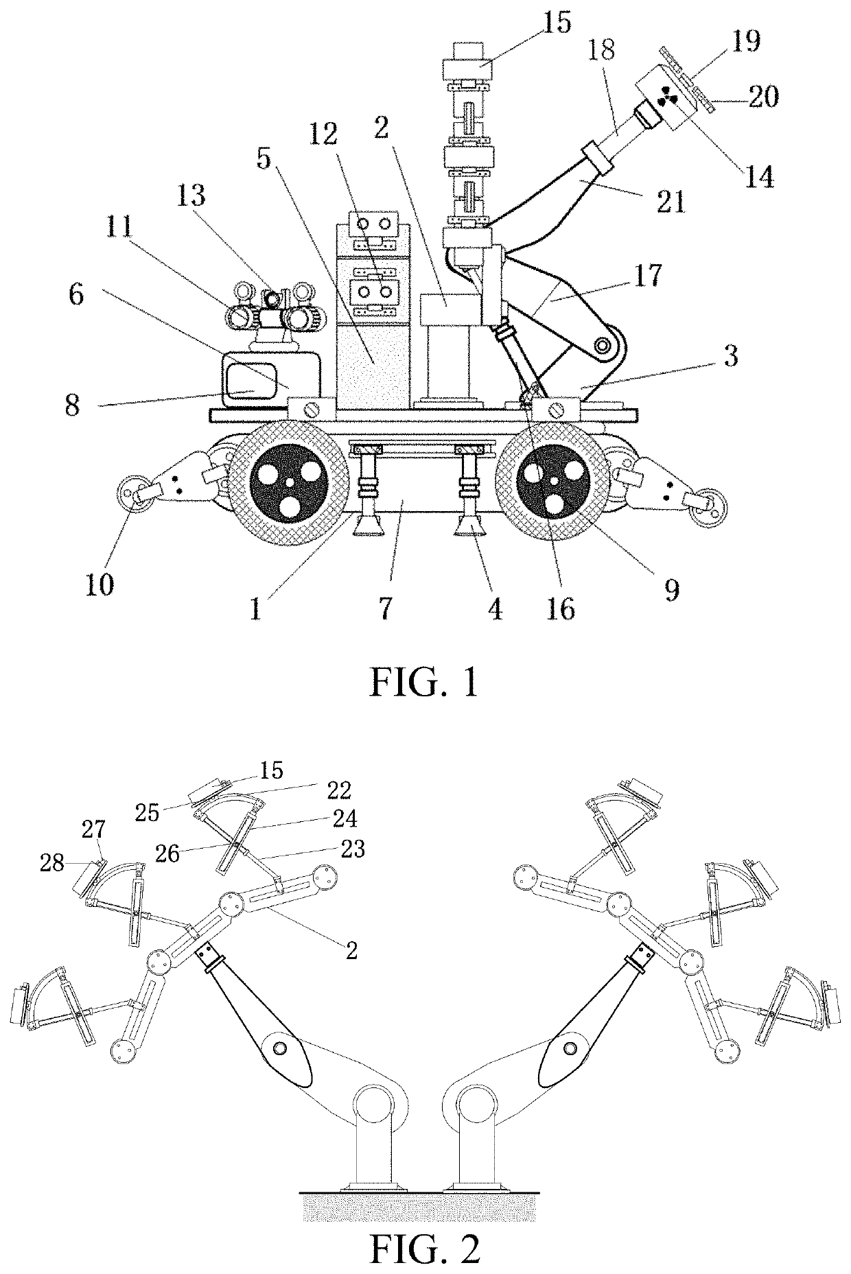
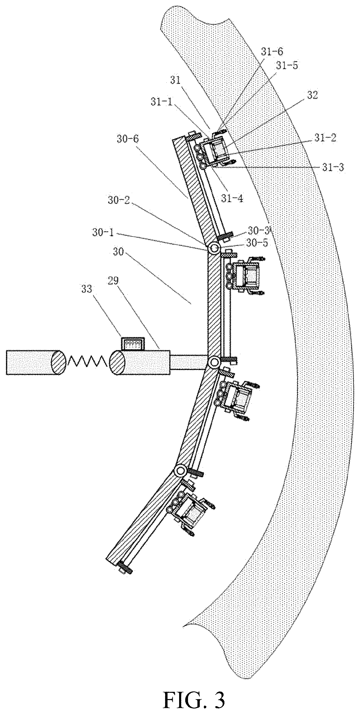
[0095]The mechanical arm is a telescopic mechanical arm 29. As shown in FIG. 3, an end of a working end of the mechanical arm, namely, an end of an extension arm, is connected to a self-adaptive floating type coupled device by using a foldable arched push-open device 2. Specifically, the mechanical arm is an industrial mechanical arm. An extension arm of the mechanical arm is configured to move the self-adaptive floating type coupled device to a position near a lining surface.

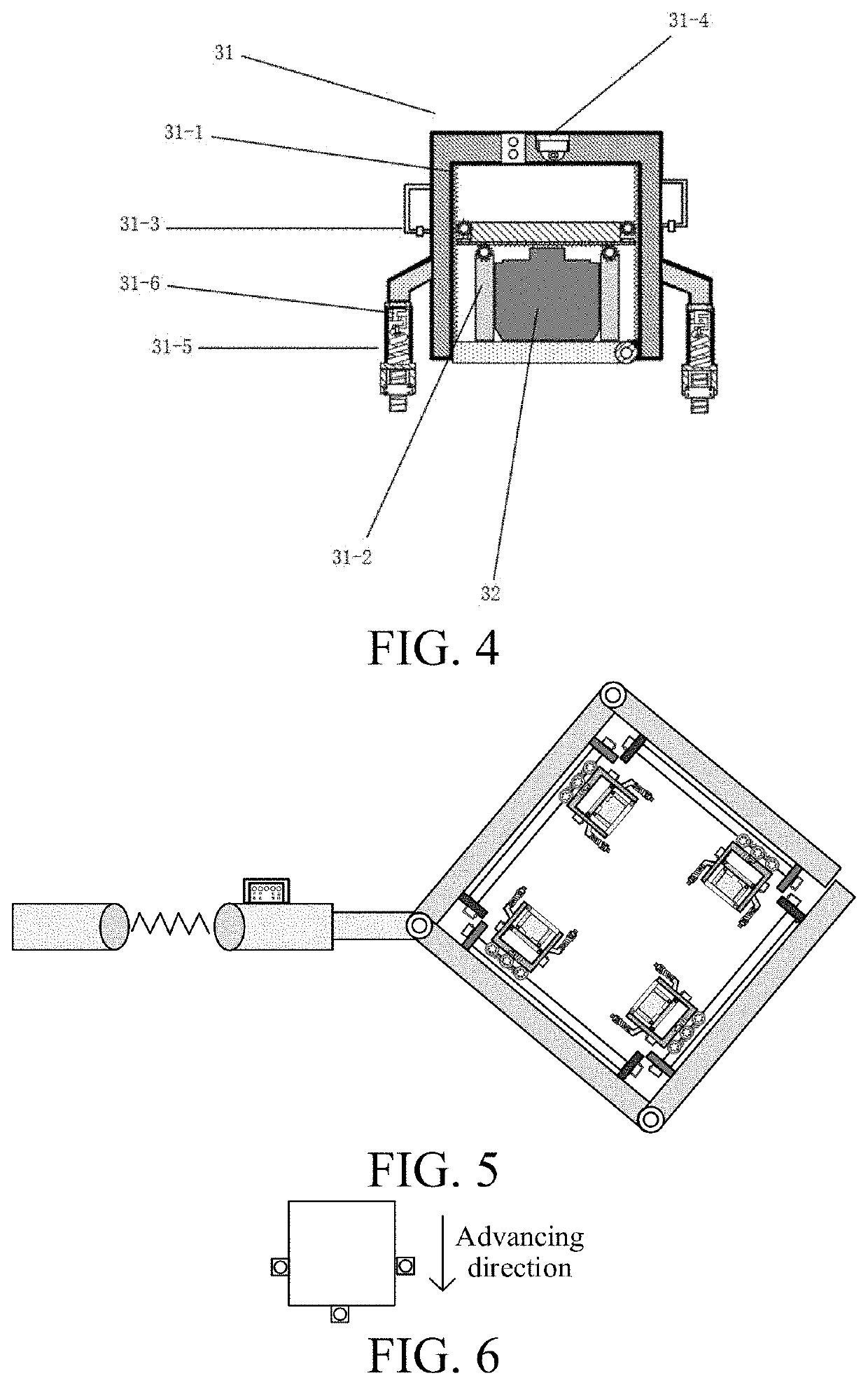
[0096]The foldable arched push-open device 30 includes a plurality of (four in this embodiment) supporting frames connected to each other, and two adjacent supporting frames are connected through rotation of a rotary shaft, and the rotary shaft is driven by a reducer; and a torque sensor is disposed on a transmission output shaft of the reducer. A hinge is furt...

embodiment 3

[0124]Based on Embodiment 1, this embodiment provides a multifunctional gimbal, to replace the line scan camera base 5 and the linear array camera array 12, and the structured light binocular stereo imaging camera 11 and the infrared thermal imaging device 13 on the robot controller 6.

[0125]As shown in FIG. 8, the multifunctional gimbal is hemispherical, and is disposed above a vehicle body by using a bracket. In this embodiment, the bracket is U-shaped, and the hemispherical multifunctional gimbal is clamped in the U-shaped bracket. Specifically, two sides of the multifunctional gimbal are separately connected to the bracket by using a lateral-roll motor, so that the gimbal can perform pitch movement. The bracket is connected above the vehicle body by using a vertical-roll motor, so that the gimbal can perform rotation in a horizontal direction.

[0126]To sense in real time and accurately control movement of the gimbal, a plurality of sensors including a three-axis gyroscope and torq...

embodiment 4

[0158]Both Embodiment 1 and Embodiment 2 relate to ground generating radars (the wideband air-coupled ground penetrating radar in Embodiment 1 is one of ground penetrating radars). This embodiment provides a deep learning-based ground penetrating radar intelligent inversion method, for implementing defect inspection based on a ground penetrating radar signal in a defect inspection process, and the method includes the following steps:

[0159]Step S1: Establish a simulated training data set, where the simulated training data set includes a plurality of ground penetrating radar sectional view-dielectric constant distribution diagram data pairs.

[0160]A corresponding simulated data set is established for the problem of inspection of defects in a tunnel lining structure. Step S1 specifically includes:

[0161]Step S101: Randomly combine background media and defect internal media, and generate a lining sectional dielectric constant distribution diagram for each combination manner. Specifically,...


PUM

PropertyMeasurementUnit
rotation angleaaaaaaaaaa
distanceaaaaaaaaaa
swing angular velocityaaaaaaaaaa

Abstract

A multi-arm robot used for tunnel lining inspection and defect diagnosis in an operation period, including a moving platform, where an environment detection device and a defect infection device are disposed on the moving platform, the defect infection device is disposed on the moving platform by using a multi-degree-of-freedom mechanical arm, and an attitude detection module is disposed on each multi-degree-of-freedom mechanical arm; a controller receives environmental data and mechanical arm attitude data sensed by the environment detection device and the attitude detection module, and sends a control instruction to the moving platform and the multi-degree-of-freedom mechanical arm according to the environmental data, to implement movement of the robot; and the controller receives tunnel lining structural data sensed by the defect infection device, and performs defect diagnosis. Overall automatic inspection can be implemented both on the surface and inside of the tunnel lining.

Description

BACKGROUNDTechnical Field[0001]The present disclosure belongs to the field of tunnel defect inspection, and in particular, to a multi-arm robot used for tunnel lining inspection and defect diagnosis in an operation period.Related Art[0002]The description in this section merely provides background information related to the present disclosure and does not necessarily constitute the prior art.[0003]With the massive construction of tunnel projects, which are successively put into operation, safe operation of the tunnel projects is particularly important. During long-term service of tunnel projects, under the effect of various factors such as natural environment and climate changes, and periodic fatigue loads such as train working, a large number of tunnel structures in an operation period have structural concealed defects such as lining cracks, reinforcing bar rusty swelling, internal voids, and water seepage and mud leakage. The defects extremely easily degrade the performance of the ...

Claims


Application Information

Patent Timeline
Patent Type & Authority Applications(United States)
IPC IPC(8): G01N21/954G01N22/02G01N23/203G01N23/20008F16L55/40G01N21/88G06N20/00
CPCG01N21/954G01N22/02G01N23/203F16L2101/30F16L55/40G01N21/8851G06N20/00G01N23/20008G06N3/08G01N21/9515G01N2021/9518G06N3/045G01N2021/9544
Inventor LIU, BINWANG, ZHENGFANGJIANG, PENGKANG, WENQIANGLIU, HANCHIZHANG, JIAQISUI, QINGMEI
Owner SHANDONG UNIV
Why Eureka
Try Eureka