
Single-phase device-multiplexing active power decoupling cascaded rectifier and control method thereof

a cascade rectifier and single-phase device technology, applied in the direction of ac-dc conversion without reversal, power conversion systems, electrical apparatus, etc., can solve the problems of poor controllability, ac-ac topology, low efficiency, etc., and achieve the effect of verifying the effectiveness of the proposed control policy

Active Publication Date: 2022-02-17
SHANDONG UNIV
View PDF0 Cites 3 Cited by
  • Summary
  • Abstract
  • Description
  • Claims
  • Application Information

AI Technical Summary

Benefits of technology

The present invention provides a device-multiplexing active power decoupling H-bridge cascaded rectifier and a control method thereof. The invention helps to reduce the secondary ripple voltage pulsation and improves the system power density. It achieves this by adding an active power decoupling branch to a single-phase H-bridge cascaded rectifier and constructing a new secondary ripple power loop by multiplexing an active power switching device without adding an additional power switching device. The invention effectively reduces the capacity of a DC-side bus voltage supported capacitor, resulting in improved performance and efficiency.

Problems solved by technology

The AC-AC topology has disadvantages such as low efficiency, poor controllability, low power quality, and relatively complex control policies.
A conventional power module of a switch has a low voltage withstand level, and a single power module cannot withstand a 27.5 kVac voltage of an electric locomotive.
However, one of inherent characteristics of a single-phase high-power factor rectifier is that a DC bus has a power pulsation that is twice a frequency of a grid-side voltage, thereby leading to large fluctuations of a secondary ripple voltage, and seriously affecting the transmission power of a converter and the voltage withstand safety of a power module.
If an electrolytic capacitor is connected thereto in parallel, a withstand voltage is low and the service life is short.
A film capacitor has a small loss, but has a large size and higher costs.
If the LC resonator is connected thereto in parallel, because the LC resonator works in a resonance state of twice a power frequency, the frequency is low, the mass and size are large, and the LC resonator is sensitive to parameters and frequency, which is not conducive to reliable and stable system operation.
Both of the methods limit an increase in power density of an on-board power electronic transformer.

Method used


Image

  • Single-phase device-multiplexing active power decoupling cascaded rectifier and control method thereof
  • Single-phase device-multiplexing active power decoupling cascaded rectifier and control method thereof
  • Single-phase device-multiplexing active power decoupling cascaded rectifier and control method thereof

Examples


embodiment 1

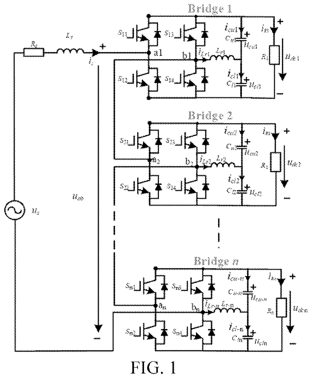
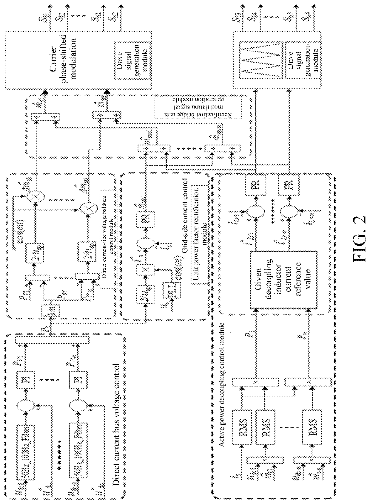
[0063]In one or more implementations, a multi-module device-multiplexing active power decoupling single-phase H-bridge cascaded rectifier is disclosed, and a topology thereof is shown in FIG. 1, including: n device-multiplexing active power decoupling H-bridge units (Bridge 1, Bridge 2, . . . , and Bridge n) that are cascaded, DC-side capacitors Cu1, Cl1, . . . , Cu-n, and Cl-n of the units being decoupling capacitors of Bridge 1, . . . , and Bridge n, and ucu1, ucl1, . . . , ucu-n, and ucl-n being decoupling capacitor voltages; Lr1, . . . , and Lrn being decoupling inductors, iLr1, . . . , and iLr-n being currents flowing through the decoupling inductors Lr1, . . . , and Lrn; and R1, . . . , and Rn being DC-side resistive loads, and udc1, . . . , and udc-n being DC-side output voltages.

[0064]A topology structure of the device-multiplexing active power decoupling H-bridge unit specifically includes: a bridge arm H1 and a bridge arm H2 connected in parallel, a decoupling capacitor br...

embodiment 2

[0094]In this embodiment, n=2, that is, a single-phase device-multiplexing active power decoupling rectifier includes two device-multiplexing active power decoupling H-bridge units that are cascaded. A control policy thereof is studied, a simulation model is built in Matlab / Simulink, and correctness and effectiveness of the proposed control policy is verified.

[0095]FIG. 6 shows a single-phase CHBR device-multiplexing active power topology with two modules cascaded. The entire system includes two single-phase H-bridge rectifier device-multiplexing active power decoupling units that are cascaded. DC-side capacitors Cu1, Cl1, Cu2, and Cl2 of the units are decoupling capacitors of Bridge 1 and Bridge 2 respectively, ucu1, ucl2, ucu2, and ucl2 are decoupling capacitor voltages; Lr1 and Lr2 are decoupling inductors, and iLr1 and iLr2 are currents flowing through the decoupling inductors Lr1 and Lr2; R1 and R2 are DC-side resistive loads, and udc1 and udc2 are DC-side output voltages.

[0096...

embodiment 3

[0107]In one or more implementations, a terminal device is provided, including a server. The server includes a memory, a processor, and a computer program stored in the memory and capable of being run on the processor, and the processor, when executing the program, implements the control policy in Embodiment 1. For brevity, details are not described herein again.

[0108]It should be understood that in this embodiment, the processor may be a central processing unit (CPU); or the processor may be another general purpose processor, a digital signal processor (DSP), an application-specific integrated circuit (ASIC), a field programmable gate array (FPGA) or another programmable logical device, a discrete gate or a transistor logical device, a discrete hardware component, or the like. The general-purpose processor may be a microprocessor, or the processor may also be any conventional processor or the like.

[0109]The memory may include a read-only memory and a random-access memory, and provi...


PUM


Abstract

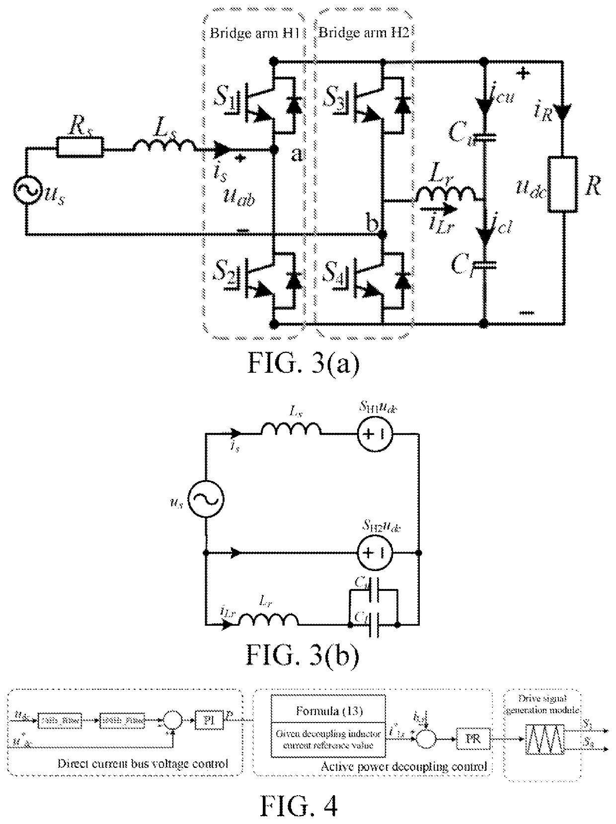
A single-phase device-multiplexing active power decoupling cascaded rectifier and control method thereof. The rectifier includes: n device-multiplexing active power decoupling H-bridge units that are cascaded, n≥2; each unit including: a bridge arm H1 and a bridge arm H2 connected in parallel, a decoupling capacitor branch formed by two capacitors connected in series, and a resistive load; a decoupling inductor being connected in series between a midpoint of the decoupling capacitor branch and a midpoint of bridge arm H2; and a bridge arm H1 of a first unit being sequentially connected in series to an inductor, resistor, and power supply, and then connected to a bridge arm H2 of a last unit. A power switch module of an H-bridge rectification unit is multiplexed, which not only realizes unit power factor rectification of the unit, but also provides a loop for secondary ripple power to achieve secondary ripple power decoupling control.

Description

BACKGROUNDTechnical Field[0001]The present invention relates to the technical field of power electronic traction transformers (PETTs), and in particular, to a single-phase device-multiplexing active power decoupling cascaded rectifier and a control method thereof.Related Art[0002]The description in this section merely provides background information related to the present invention and does not necessarily constitute the prior art.[0003]PETT converts a power frequency alternating current (AC) transformer into a medium-high frequency transformer by using a power electronic conversion technology, to achieve electrical isolation and voltage class conversion, which has advantages such as a small size, a light weight, and a high power density as compared with a power frequency transformer. The topology structure of PETT mainly includes two major types: an AC-AC direct conversion topology and an AC-direct current (DC)-AC topology. The AC-AC topology has disadvantages such as low efficienc...

Claims


Application Information

Patent Timeline
IPC IPC(8): H02M7/219H02M1/00H02M7/04
CPCH02M7/219H02M7/05H02M1/007H02M7/217H02M1/0074H02M1/008H02M1/15H02M1/4233H02M1/0043H02M1/0003H02M7/4833
Inventor DU, CHUNSHUI
Owner SHANDONG UNIV
Learn More