Metal structures

a metal structure and metal technology, applied in the field of metal structure obtaining method, can solve the problems of limiting the practical applicability of metal structure, exposing the structure's mechanical fragility, and inherently poor mechanical stability of metal structure, and achieves the effects of reducing tortuosity, reducing mechanical fragility, and superior fluid permeability

Pending Publication Date: 2022-03-10
ROYAL MELBOURNE INST OF TECH
View PDF0 Cites 2 Cited by
  • Summary
  • Abstract
  • Description
  • Claims
  • Application Information

AI Technical Summary

Benefits of technology

[0011]Further, the unique geometry of the network of dendritic channels offers superior fluid permeability relative to conventional porous metal structures thanks to its high specific surface area and interconnectivity. By the specific nature of their formation mechanism, the dendrites form in a lattice-like configuration. Upon dealloying, the dendrites are removed leaving a highly directional network of dendritic channels characterised by reduced tortuosity, improved permeability, and / or enhanced mechanical stability relative to conventional porous metal structures. Those characteristics advantageously confer the structures of the present invention with superior capability for smooth mass transfer combined with high mechanical stability.
[0012]In addition, by relying on the spontaneous formation of dendrites during cooling of the alloy, the method of the invention offers a procedure for the fabrication of structures with intricate porosity that can be significantly streamlined relative to conventional techniques.

Problems solved by technology

However, while those multi-step dealloying procedures offer some fabrication flexibility, the resulting metal structures suffer from inherently poor mechanical stability.
This effectively limits the practical applicability of those structures in fluid treatment applications (e.g. filtration) due to the significant flow back pressure they generate during use, which further exposes the structures' mechanical fragility.
In addition, the multi-step nature of conventional filler / templates approaches makes them inherently complex and limits their applicability on a large scale.

Method used


Image

  • Metal structures
  • Metal structures
  • Metal structures

Examples


example 1

[0097]The alloy melt was prepared by assembling the raw materials in a water-cooled crucible. The crucible was evacuated and partially backfilled with inert gas prior to being heated under reduced pressure until the materials were molten.

[0098]Suction-cast arc-melted precursor alloy rods were sectioned into small circular disks for repeatable data. Two alloy systems containing different noble metals (Cu30Mn70 and Au30Co70) were used as precursors. Nanoporous Cu disks of equal geometry were produced by free corrosion in 1M HCl, while nanoporous Au samples were produced by free corrosion in 10M HNO3.

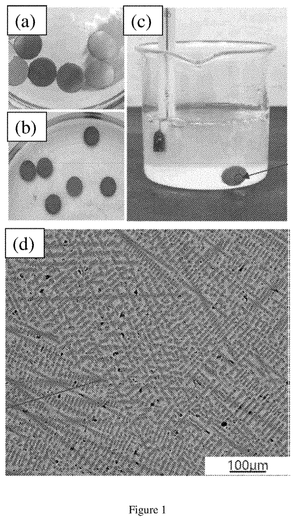
[0099]FIGS. 1(a)-(c) show pictures of different steps of an embodiment method of the invention. FIG. 1(a) shows precursor alloy disks obtained by sectioning solidified alloy rods. FIG. 1(b) shows as-dealloyed porous copper disks. FIG. 1(c) shows an image of one of the samples immersed in the dealloying solution. The image refers to the chemical dealloying process to selectively remove Mn f...

example 2

ty Characterisation

[0106]Contact angle measurements were conducted on dealloyed Cu structures obtained in accordance with the procedure described in Example 1. Measurements were conducted on a KSV CAM 200 Tensiometer under standard conditions.

[0107]Contact angle measurements confirmed that the tested copper samples are super-hydrophilic, with contact angle of 0° (as shown in FIG. 6(b)) relative to a contact angle of 76.8° measured on dense Cu samples (as shown in FIG. 6(a)). With regard to the porous Cu structures it is evident from the test that water droplets rapidly wick into the sample structure and evenly disperse in all directions due to large capillary forces due to the multi-modal porosity of the sample structure.

[0108]Super-hydrophilicity can be particularly useful for maximum wicking and surface wetting in applications such as heat transfer (i.e. for surface rewetting yielding maximum heat transfer coefficient and heat flux removal), and for wicking of water (i.e. for evap...

example 3

rial Tests

[0109]The antibacterial properties of dealloyed Cu structures, obtained in accordance with the procedure described in Example 1, were examined. Specifically, the antimicrobial activity towards a representative bacterium, Staphylococcus Aureus, was examined. Stainless steel and dense Cu were used as negative and positive controls, respectively.

[0110]Serial dilution, agar plating and colony counting was performed in order to accurately quantify the remaining viable bacteria after exposure to metal substrates of the invention and the reference controls. FIG. 7(a)-(c) show serial dilution and plating of Staphylococcus Aureus bacteria on Tryptic Soy Agar (TSA) plates after 2 minutes of incubation with exposure to (a) stainless steel (b) dense copper and (c) porous copper disks obtained in accordance with the invention. For each petri dish shown in FIGS. 7(a)-(c), each quadrant represents a dilution factor, ranging from 1 to 10−3. Group of colonies (5×10 uL droplet of bacterial ...


PUM

PropertyMeasurementUnit
temperatureaaaaaaaaaa
cross-sectional sizeaaaaaaaaaa
sizeaaaaaaaaaa

Abstract

A method for producing a metal structure comprising a porous inter-dendritic matrix defining a network of dendritic channels, the method comprising the steps of: preparing an alloy melt comprising a metal element and at least one alloying element, cooling the alloy melt to a solid alloy, wherein the cooling promotes formation of a network of dendrites rich in the at least one alloying element within an inter-dendritic matrix rich in the metal, dealloying the solid alloy to remove alloying element from the dendrites and the inter-dendritic matrix to obtain the metal structure.

Description

FIELD OF THE INVENTION[0001]The invention relates generally to a method for obtaining a metal structure, the metal structure, and an antimicrobial device comprising the metal structure. The metal structure can have a multimodal pore size distribution.BACKGROUND OF THE INVENTION[0002]Considerable research effort has been directed over the years to developing structures made of porous metal for specific industrial needs. Existing procedures for the fabrication of porous metals include dealloying of solid solution alloys. In essence, dealloying refers to the selective leaching of one or more elements out of a solid solution alloy to produce a residual porous structure. The left-over structure is rich with the element that is less reactive to the leaching medium (i.e. nobler) and presents a three-dimensional network of voids left by the removed more active element(s) (i.e. less noble). Dealloying procedures have conventionally been used to fabricate porous metal structures characterized...

Claims


Application Information

Patent Timeline
Patent Type & Authority Applications(United States)
IPC IPC(8): C22C3/00C23F1/18C23F1/30C25F3/02C22C9/05
CPCC22C3/00C23F1/18C22C9/05C25F3/02C23F1/30B82Y30/00B82Y40/00C22C5/02C22C9/00C23F1/00
Inventor SMITH, JACKSON LEIGHQIAN, MASONG, TINGTINGLIANG, DANIEL
Owner ROYAL MELBOURNE INST OF TECH
Why Eureka
Try Eureka