WELDING FILLER WIRE FOR FUSION WELDING PRECIPITATION-HARDENED AUSTENITIC Fe-Mn-Al-C ALLOYS

Active Publication Date: 2022-03-17
FANG TE FU +1
View PDF4 Cites 2 Cited by
  • Summary
  • Abstract
  • Description
  • Claims
  • Application Information

AI Technical Summary

Benefits of technology

[0031](3) By the addition of appropriate amount of Ti, Nb and V to the welding filler, in the as-welded condition, in addition to the high-density of nano-sized κ-carbides existing within the austenite dendrite cells and eutectic regions, there are a significant amount of nano-sized (˜6-10 nm) Ti-rich Ti-carbides, Nb-rich Nb-carbides, V-rich V-carbides formed within the eutectic regions. These carbides are all having the same ductile face-centered-cubic (FCC) structure as the austenite. Moreover, the hardnesses of these carbides are extremely high, reaching ˜2000-3500 Hv. As a consequence, the hardn

Problems solved by technology

As a result, the fusion welding has inevitably resulted in severe softening of the FZ.
In addition, the FZ is also the region most susceptible to hot cracking effects (e.g. solidification and liquation cracking) and formation of porosities.
As a matter of fact, for those acquainted with this field, these three major issues have been remaining as very challenging, if not insurmountable, obstacles yet to be resolved in fusion welding the precipitation-hardened alloys.
However, for fusion welding the precipitation-hardened austenitic Fe—Mn—Al—C alloys, similar to other precipitation-hardened alloys, challenges, such as severe softening in FZ, hot cracking (e.g. solidifica

Method used


Image

  • WELDING FILLER WIRE FOR FUSION WELDING PRECIPITATION-HARDENED AUSTENITIC Fe-Mn-Al-C ALLOYS
  • WELDING FILLER WIRE FOR FUSION WELDING PRECIPITATION-HARDENED AUSTENITIC Fe-Mn-Al-C ALLOYS
  • WELDING FILLER WIRE FOR FUSION WELDING PRECIPITATION-HARDENED AUSTENITIC Fe-Mn-Al-C ALLOYS

Examples


example 1

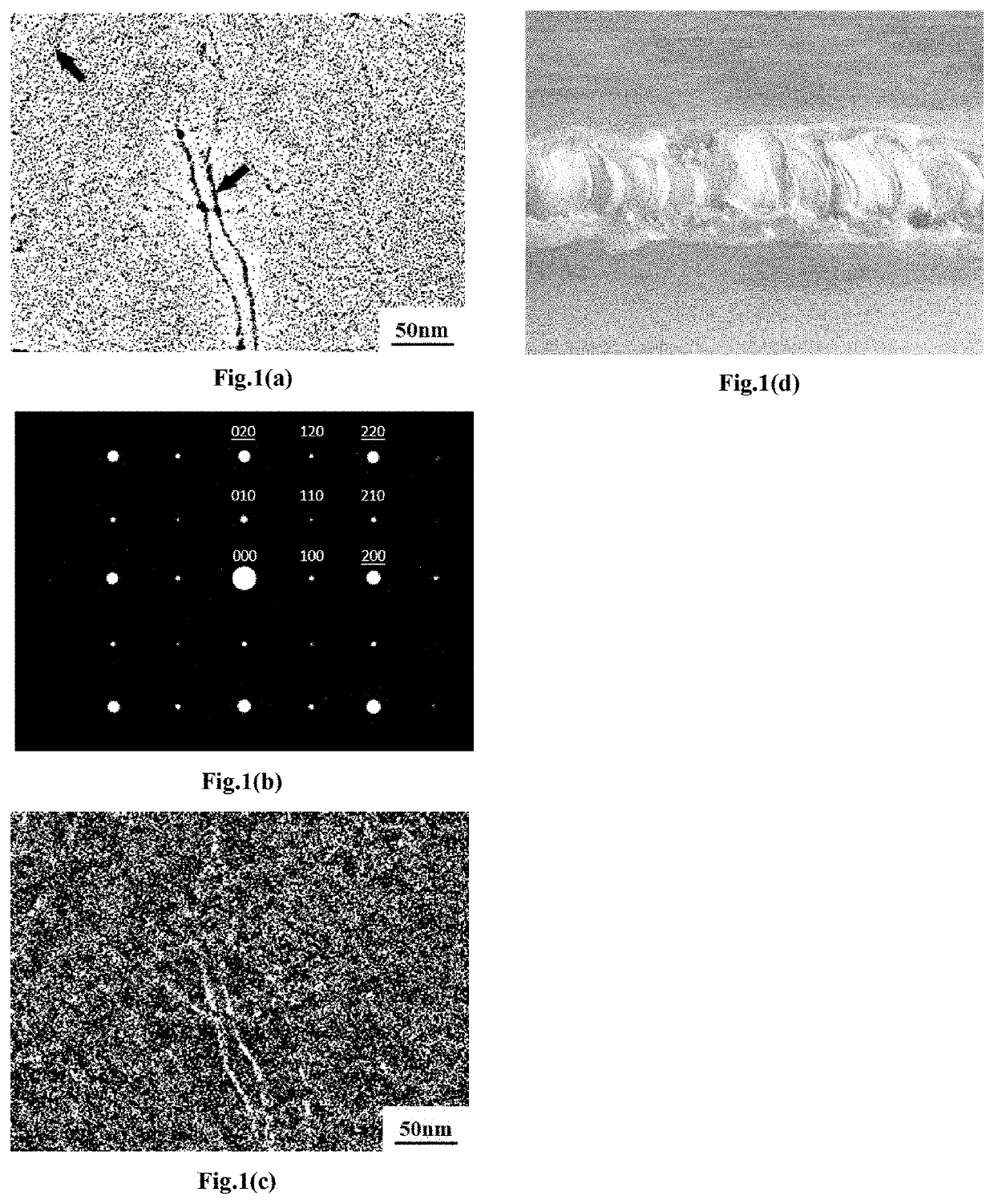
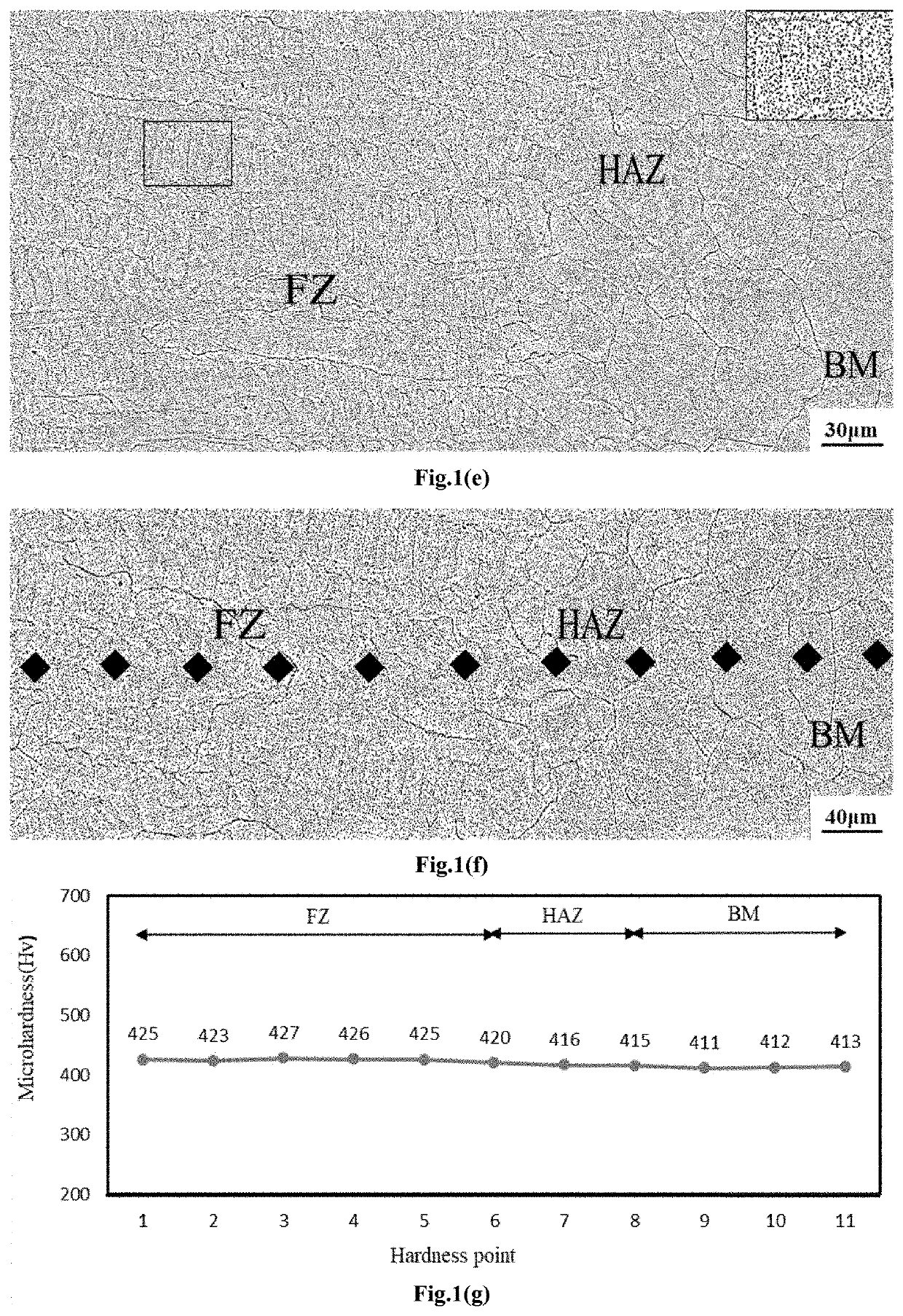
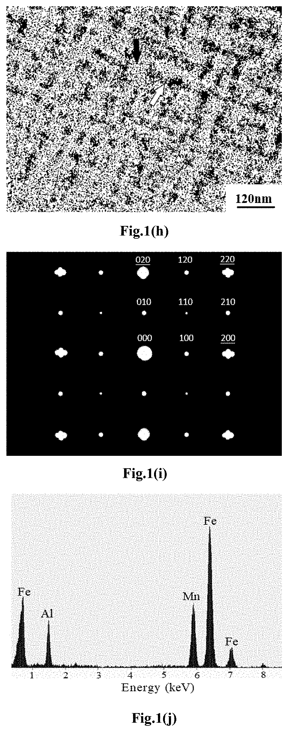
[0136]FIG. 1(a) is the TEM bright field (BF) image of an as-hot-rolled Fe-28.5Mn-9.0Al-1.55C base material, showing a high-density of nano-sized (˜3-5 nm) precipitates uniformly distributing within the matrix. Also noted that, as indicated by the arrows shown in FIG. 1(a), the precipitates existing on the dislocations are slightly larger in size (˜5-8 nm), suggesting that these precipitates were formed during the hot-rolling process. FIG. 1(b), the selected-area diffraction pattern (SADP) of the as-hot-rolled base material, demonstrates that the high-density of nano-sized precipitates are (Fe,Mn)3AlC carbides (κ-carbides) having an L′12-structure. FIG. 1(c) shows the (100)K dark field (DF) image of the same area as displayed in FIG. 1(a) to illustrate the presence of the κ-carbides within the austenite matrix and on the dislocations. It is clear that the as-hot-rolled microstructure of the base material used in the present embodiment is single-phase austenite with uniformly distribu...

example 2

[0142]The purpose of the present Example attempts to clarify the effects of altering the carbon content in the welding filler wire on the characteristics of FZ in the as-welded sample. The base material used in this Example was the same as that used in Example 1. However, the GMAW welding process was employed in this Example. The dimensions of the BM plates were 80 mm×80 mm×12 mm, which were machined to form a single V-groove butt weld. The GMAW welding process was carried out with a voltage of 26 V and current of 140˜170 A. The flow rate of the shielding gas (25% Ar+75% He) was ˜18 liters / min and the welding filler wire feeding speed of was ˜200 mm / min, respectively. The nominal composition of the welding filler wire used in the present Example was Fe-28.2Mn-9.2Al-1.72C with a wire diameter ϕ˜1.2 mm.

[0143]FIG. 2(a) shows the macroscale image of the GMAW welding bead. It can be seen from FIG. 2(a) that the bead appears to have a very smooth morphology with no visible macrocrack and ...

example 3

[0147]In this Example, we investigated the effects of a slightly lower carbon content on the characteristics FZ in the as-welded sample. An as-hot-rolled base material with nominal composition of Fe-28.8Mn-8.9Al-1.62C was used in the present Example of embodiment. FIG. 3(a) is the TEM BF image of the hot-rolled base material. It is evident in FIG. 3(a) that the as-hot-rolled microstructure of BM used in the present Example is quite similar to that used in Example 1 and Example 2. Namely, there is a high-density of nano-sized (˜3-5 nm) precipitates uniformly distributing within the matrix and on the dislocations (as indicated by the arrows). FIG. 3(b) is the selected-area diffraction pattern (SADP) of the as-hot-rolled base material, which evidently confirms that the matrix of the base material is fully austenitic and the high-density nano-sized precipitates are the ordered L′12-structured κ-carbides. FIG. 3(c) is the (100)K DF image taken from the same area as displayed in FIG. 3(a)...


PUM

PropertyMeasurementUnit
Fractionaaaaaaaaaa
Fractionaaaaaaaaaa
Fractionaaaaaaaaaa

Abstract

A series of welding filler wires with innovative composition design for fusion welding precipitation-hardened lightweight austenitic Fe—Mn—Al—C alloys. The first class of the welding filler wires is composed of 23-34 wt. % Mn, 7.5-11.5 wt. % Al, 1.35-1.95 wt. % C, with the balance being essentially Fe. After fusion welding, there are high-density of nano-sized (˜3-5 nm) (Fe,Mn)3AlC carbides (κ-carbides) uniformly distributed within the austenite dendrite cells in the fusion zone (FZ). The amount of nano-sized (˜6-10 nm) κ-carbides existing within the eutectic regions is significantly increased and the size of the austenite dendrite cells is substantially reduced. The second class of welding filler wires has the composition of 23-34 wt. % Mn, 7.5-11.5 wt. % Al, 1.40-1.95 wt. % C, 0.1-2.5 wt. % Ti, 0.1-3.0 wt. % Nb, 0.1-2.5 wt. % V, with the balance being essentially Fe. The microstructure of the FZ in the as-welded condition results in formation of substantial amount of nano-sized (˜6-10 nm) face-centered-cubic structured ductile Ti-rich Ti-carbides, Nb-rich Nb-carbides and V-rich V-carbides within the eutectic regions. These carbides are extremely hard (2000˜3500 Hv), enhancing hardness of the obtained FZ.

Description

BACKGROUND OF THE INVENTIONField of the Invention[0001]The invention relates to disclosure of innovative welding filler wires for joining components made of precipitation-hardened lightweight Fe—Mn—Al—C alloys, in particular, by fusion welding utilizing gas tungsten arc welding (GTAW) and gas metal arc welding (GMAW).Description of the Prior Art[0002]Precipitation hardening (or age hardening) is the heat treatment technique used to increase the yield strength (YS) and hardness of malleable alloys, such as the strongest 7xxx-series aluminum alloys (e.g. AA7075), the precipitation-hardened stainless steels, and the precipitation-hardened austenitic Fe—Mn—Al—C alloys, etc. The precipitation-hardening process involves three basic steps: solution-heat-treatment (SHT), quenching and aging. The first step (SHT) is to heat the alloy to a temperature above the solvus temperature and soak there until a homogeneous “single-phase” solid solution is produced. The second step (quenching) is to co...

Claims


Application Information

Patent Timeline
IPC IPC(8): B23K35/02B23K35/30C22C38/04C22C38/06C22C38/12C22C38/14C21D6/02
CPCB23K35/0261B23K35/3073C22C38/04C21D2211/001C22C38/12C22C38/14C21D6/02C22C38/06B23K9/167B23K9/32B23K9/23B23K9/02B23K35/3053B23K9/173B23K2103/04C22C38/38
Inventor LIU, TZENG-FENG
Owner FANG TE FU
Why Eureka
Try Eureka