Polymeric salt bridges for conducting electric current in microfluidic devices

Active Publication Date: 2009-11-17
SANDIA NAT LAB
View PDF22 Cites 1 Cited by
  • Summary
  • Abstract
  • Description
  • Claims
  • Application Information

AI Technical Summary

Benefits of technology

[0008]Microporous polymer salt bridges as disclosed herein allow such structures to be fabricated in a desired microchannel, by injection of solution into a specified region of a three dimensional microfluidic device structure (typically an insulator such as glass, coated silicon, or plastic) in an unpolymerized state, and by subsequent formation in place of the polymer structure by a polymerization step initiated via a suitable method such as a UV or thermal cure process. If desired, the solvents within the polymeric salt bridge structures can be exchanged by diffusion before or during operation of the microdevice. In one embodiment, such a microporous polymer salt bridge can be physically secured to a glass substrate to provide for resistance against high fluid p

Problems solved by technology

Metal electrodes are generally undesirable or impractical in microfluidic devices becau

Method used


Image

  • Polymeric salt bridges for conducting electric current in microfluidic devices
  • Polymeric salt bridges for conducting electric current in microfluidic devices
  • Polymeric salt bridges for conducting electric current in microfluidic devices

Examples


Example

EXAMPLE 1

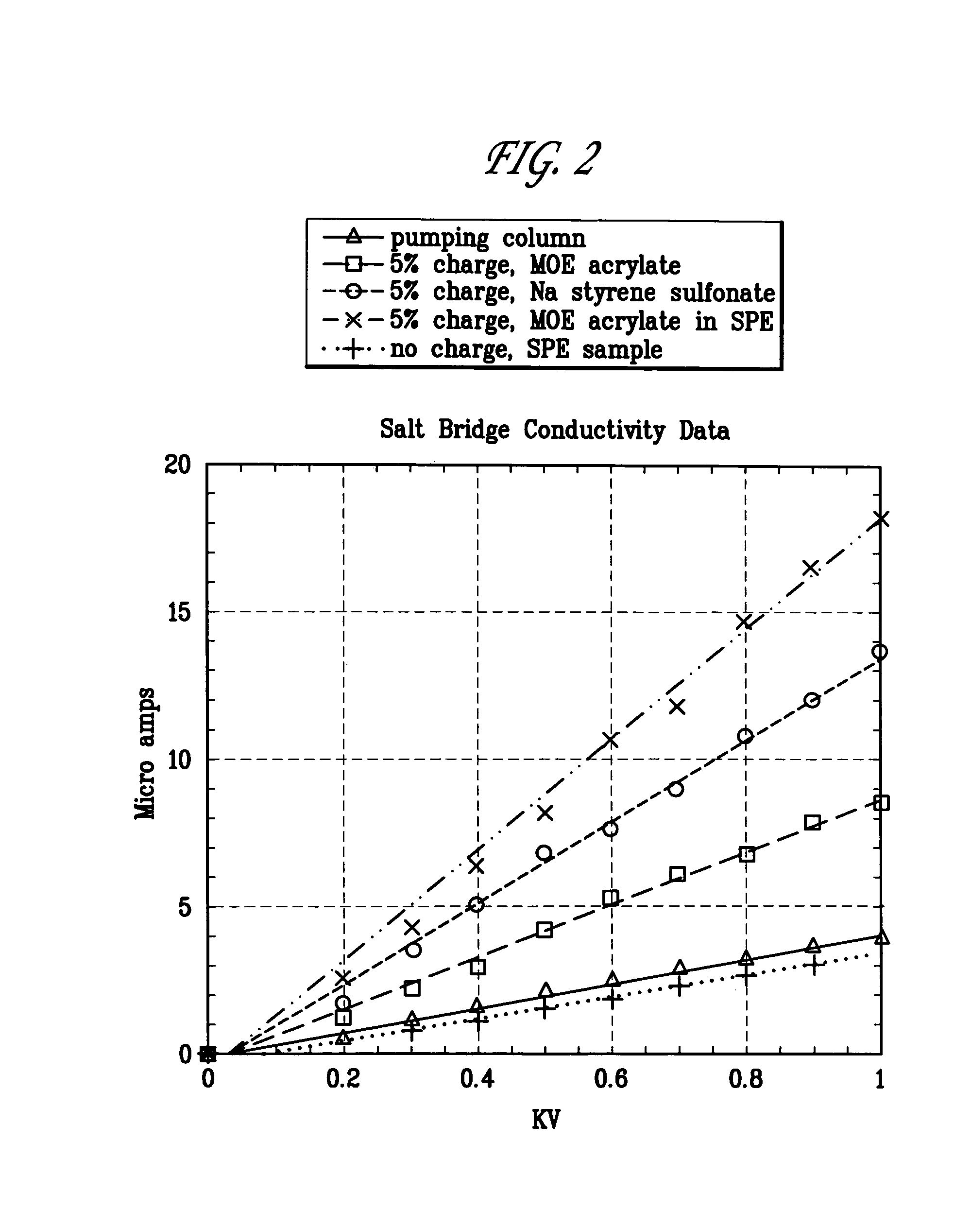
[0045]A positively charged salt bridge was prepared by using the following constituents:

[0046]QTYCONSTITUENTWEIGHT % CONSTITUENT2.437mlTris buffer, (pH 8, 5 mM)50.00.313mlMOE (acrylate monomer),5.080% in water1.325mlHEA (acrylate monomer)26.50.8mlSR-9035 (cross-linker)16.00.125gMBA (cross-linker)2.5

[0047]A first monomer MOE and a second monomer HEA were combined with a first cross-linker SR-9035 and a second cross-linker MBA in a Tris buffer solution at pH 8. Then, 15 ml ammonium persulfate initiator was added and the mixture was injected into a microchannel and polymerized.

[0048]The formulation just described in this Example 1 can be altered to vary the charge concentration as needed by changing the amount of MOE, and adjusting the HEA to achieve a desired monomer / solvent ratio. Conductivity can also be increased by reducing the monomer concentration to as much as 40% of the total volume, which in one embodiment may be accomplished by reducing equal amounts of HEA and SR-9...

Example

EXAMPLE 2

[0049]A negatively charged salt bridge can be prepared by using the following constituents:

[0050]QTYCONSTITUENTWEIGHT % CONSTITUENT2.5mlTris buffer, (pH 8, 5 mM)50.00.25gSSS (monomer), 80% in water5.01.325mlHEA (acrylate monomer)26.50.8mlSR-9035 (cross-linker)16.00.125gMBA (cross-linker)2.5

[0051]A first monomer SSS and a second monomer HEA were combined with a first cross-linker SR-9035 and a second cross-linker MBA in an aqueous Tris buffer solution. Then, 15 ml ammonium persulfate initiator was added and the mixture injected into a microchannel and polymerized, preferably by UV cure.

Example

EXAMPLE 3

[0052]A salt bridge was prepared by providing mixture using the following constituents:

[0053]QTYCONSTITUENTWEIGHT % CONSTITUENT3.0mlTris buffer (pH 8, 5 mM)72.30.15gMBA (cross-linker)3.61.0gSPE (monomer)24.1

[0054]A first monomer SPE and a first crosslinker MBA were provided well mixed in an aqueous Tris buffer solution. Then, 8 ml of ammonium persulfate initiator was added and the mixture injected into a microchannel and polymerized by UV cure. The salt bridge provided by this formulation cures quickly. Also, this formulation is useful in some applications because it does not release any mobile ions into solution, and thus minimizes the impact of the salt bridge on other analytical procedures. However, the large buffer content and low monomer concentration and cross-link density results in provision of a bulk sample that is somewhat fragile in comparison to the salt bridges produced in Examples 1 and 2.


PUM


Abstract

A “cast-in-place” monolithic microporous polymer salt bridge for conducting electrical current in microfluidic devices, and methods for manufacture thereof is disclosed. Polymeric salt bridges are formed in place in capillaries or microchannels. Formulations are prepared with monomer, suitable cross-linkers, solvent, and a thermal or radiation responsive initiator. The formulation is placed in a desired location and then suitable radiation such as UV light is used to polymerize the salt bridge within a desired structural location. Embodiments are provided wherein the polymeric salt bridges have sufficient porosity to allow ionic migration without bulk flow of solvents therethrough. The salt bridges form barriers that seal against fluid pressures in excess of 5000 pounds per square inch. The salt bridges can be formulated for carriage of suitable amperage at a desired voltage, and thus microfluidic devices using such salt bridges can be specifically constructed to meet selected analytical requirements.

Description

STATEMENT OF GOVERNMENT INTEREST[0001]The United States Government has rights in this invention pursuant to Contract No. DE-AC04-94AL85000 between the United States Department of Energy and Lockheed Martin Corporation for the management and operation of Sandia National Laboratories.FIELD OF THE INVENTION[0002]The invention is directed generally to novel devices for enabling the flow of electricity in microfluidic systems. More particularly, the invention is directed to electrically conductive structures for use in microfluidic devices, and to methods for fabrication and in-situ formation of electrically conductive structures in microfluidic devices, wherein such electrically conductive structures have preselected electrical, chemical, and structural properties.BACKGROUND OF THE INVENTION[0003]Development of miniaturized microfluidic systems has resulted in the ever increasing use of microanalytical devices that are able to perform a multitude of chemical, physical, and / or electrical...

Claims


Application Information

Patent Timeline
IPC IPC(8): G01N27/453
CPCB01L3/502707B01L3/502738F04B19/006B01L2200/143B01L2400/0418B01L2400/0421B01L2300/0816
Inventor SHEPODD, TIMOTHY J.TICHENOR, MARK S.ARTAU, ALEXANDER
Owner SANDIA NAT LAB
Why Eureka
Try Eureka