Accordingly, in the bottom portion of a blast furnace (bosh portion, steeply rising portion, and bottom shaft portion) in which melted
slag exists as a high
thermal load region, the stave body is prone to
cracking due to a high thermal stress on the stave body resulting in
water leakage from cracks transferred to cooling pipes.
In order to prevent the cooling pipes from
cracking, a boundary between the cooling pipes and cast-iron portion is generally made unfused; however, this results in further reduction in the
cooling capacity of the stave.
However, these are not preferable because of complexity in the stave structure and an increase in the manufacturing cost of the stave.
Even in these countermeasures, the cooling capacity is not sufficient when applied to the bottom portion of a blast furnace, which is a high
thermal load region.
Therefore, these problems are actualized when harsh demands are made such as an extended life of a blast furnace, and severe operating conditions by blowing-in of a large amount of pulverized
coal.
However, these conventional
copper staves have the following problems.
A stave made of copper obtained by
machining rolled or forged copper has disadvantages such as high manufacturing cost due to complex
machining and a small degree of freedom in its shape.
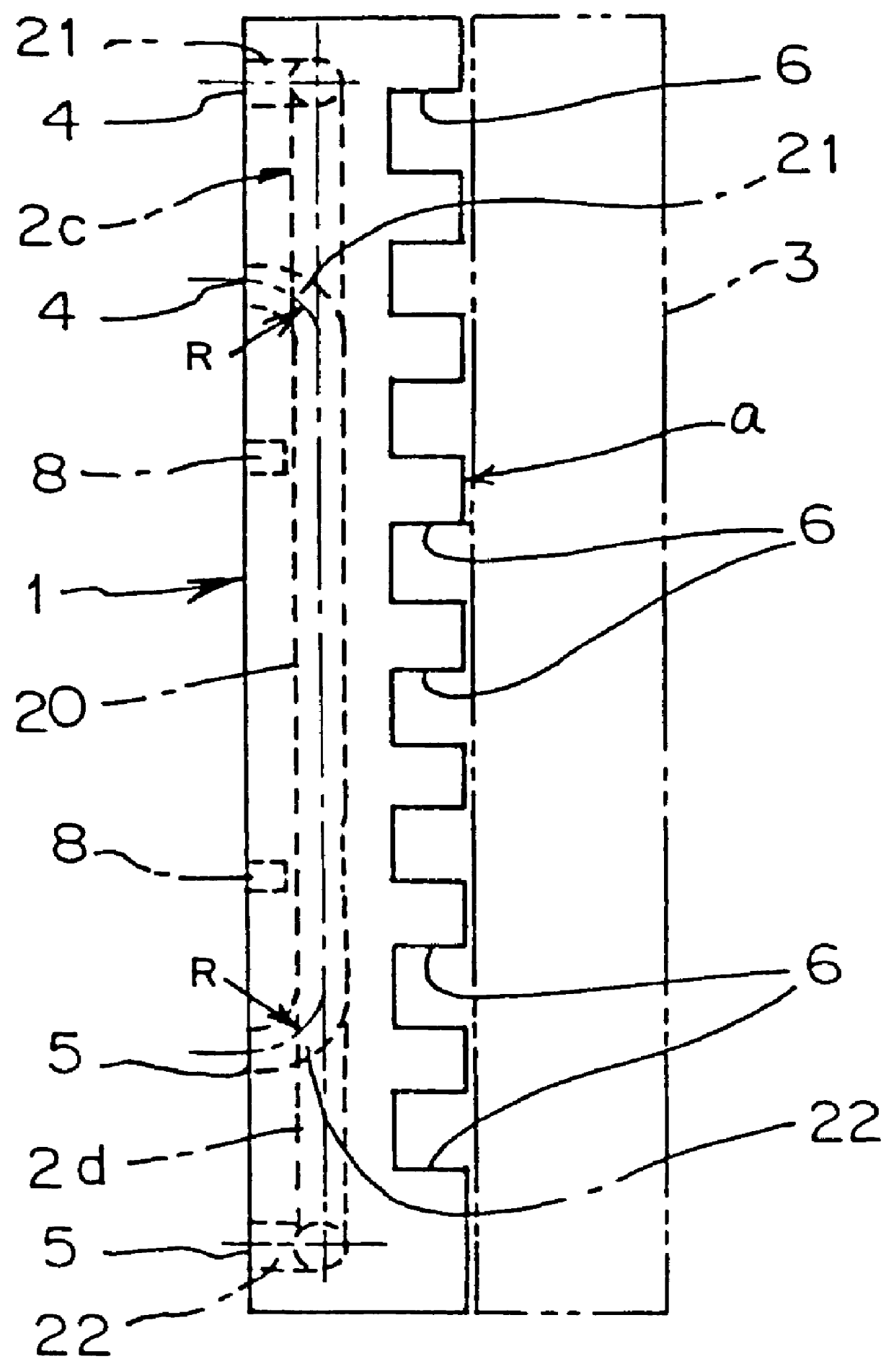
(1) While a curvature of the stave body is necessary in accordance with the inner
diameter of the furnace, it is very difficult for such a curvature to be economically formed when the stave is machined from a material such as rolled copper. Accordingly, the stave body is unavoidably designed in a flat shape, reducing an operating volume of the furnace.
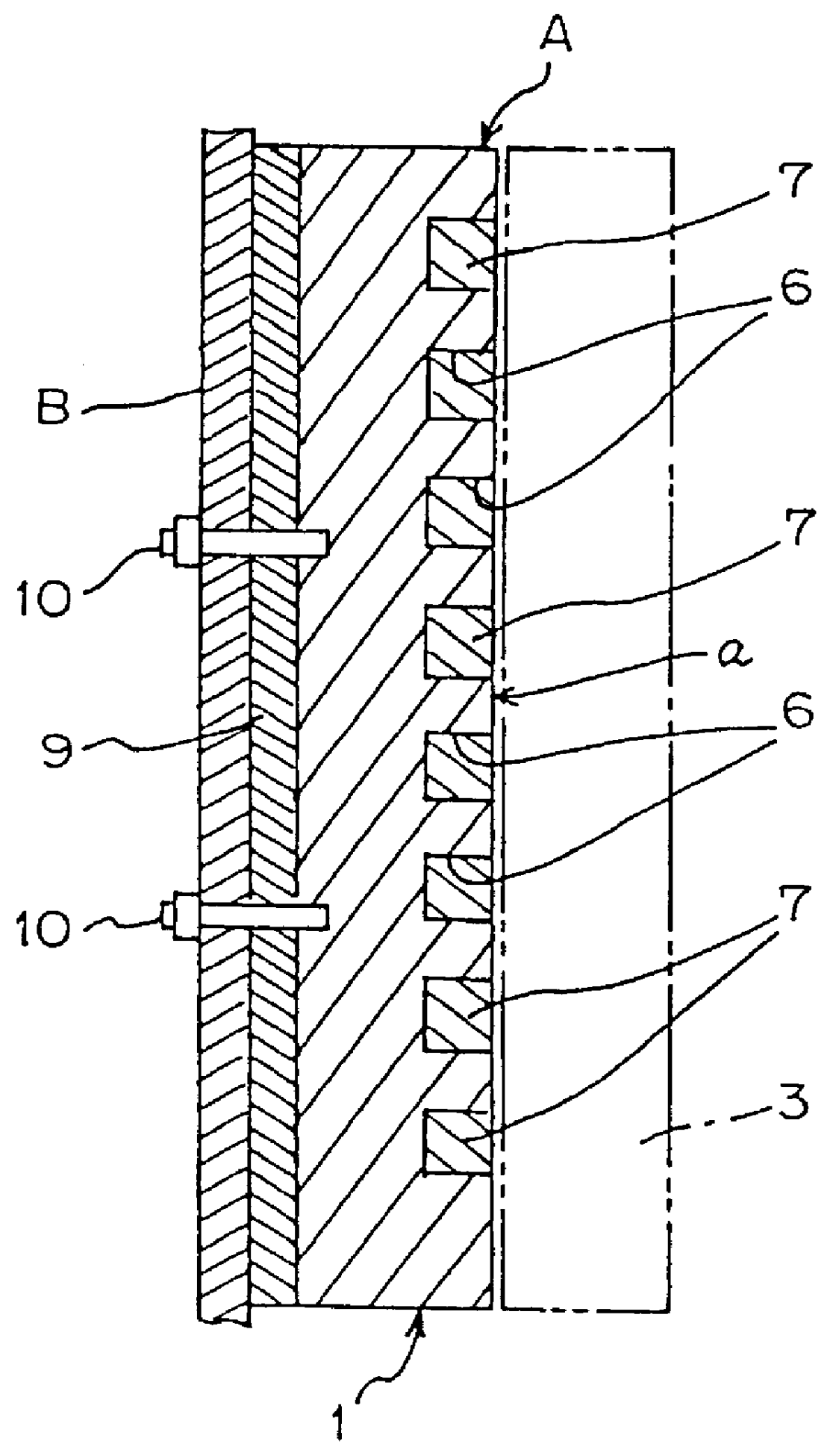
(2) It is necessary to form bosses and ribs for fixing the back of the stave to a shell of the furnace. These parts must be separately machined and welded, increasing the manufacturing cost.
(3) When protrusions or grooves for holding furnace refractories and coagulated
slag are formed in a cooling surface of the inside of the furnace, these must be machined from a
thick plate, increasing the manufacturing cost.
(4) When new copper staves are placed in an existing furnace having
cast iron staves to be used in combination with the existing
cast iron staves, the thickness of the copper staves must agree with that of the
cast iron stave to maintain the profile of the inside of the furnace. In this case, the thickness of the copper stave is up to 250 mm, resulting in high cost
machining from a material such as rolled copper. Occasionally, such a thick material cannot be obtained.
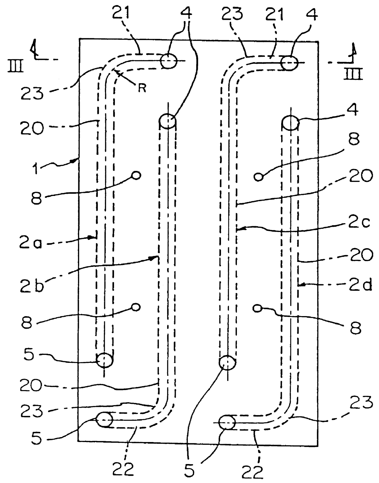
(5) When copper staves are applied to the portion of a furnace between a belly (steeply rising portion) and a shaft, it is necessary to form the stave in an elbowed shape in a vertical direction, increasing the manufacturing cost by machining and bending.
Since the corner portion formed in this manner is L-shaped, head loss of a
coolant (normally, cooling water) flowing therethrough is increased to increase
energy loss.
Furthermore, in this L-shaped corner portion, the cooling water stagnates and is prone to produce deposits on an inner surface of the path in this region.
When these deposits successively accumulate, this increases head loss of cooling water and decreases
thermal conductivity between the cooling water and the stave, reducing the cooling capacity by cooling water.
Furthermore, when the the cooling water stagnates as described above, air bubbles are produced by turbulent flow of the cooling water to reduce the cooling capacity.
The above-mentioned increased head loss affects the velocity of the cooling water, reducing the stave functions along with the above-mentioned reduced cooling capacity.
Due to the clearance,
thermal conduction is not sufficient between the
cooling pipe and the
casting, thereby being prone to failure of the casting due to a thermal load from the inside of the furnace.
(2) The
cooling pipe may be recrystallized by a casting heat to reduce the strength of the cooling
pipe, resulting in breaking of the
pipe.
(3) Since the
melting point of the cooling pipe and that of the cast copper are the same, the cooling pipe may be dissolved and damaged, depending on the casting temperature.
To avoid this, when the casting temperature is reduced, a defect caused by gas is prone to occur.
(4) In order to form a path for a coolant inside the stave, it is necessary to bend the cooling pipe with a high accuracy and occasionally bend to it in a complicated shape, resulting in increased manufacturing cost.
(5) When a cooling pipe is packed by insert casting, it is difficult to accurately position the pipe to obtain the product as designed.
In the bending portion of the cooling pipe especially, a curvature before casting may be increased, reducing dimension accuracy.
(1) While quantity of the cooling water which can be supplied to each stave has a predetermined limit due to the capacity of a pump, because of a large cross-sectional area of a path for a coolant in a jacket-type copper-made stave, the velocity of the cooling water is inevitably reduced. In order to
resist the thermal load from a furnace, the velocity of cooling water is required to be approximately 1 to 3 m / sec. In a jacket-type cast copper stave, the velocity may be up to 1 m / sec (no less than 0.3 m / sec if less than 1 m / sec, in general). This may result in damage by
dissolution of the stave due to the thermal load from the furnace.
(2) In a jacket-type cast copper stave, independent multiple lines of the cooling paths will be complicated in structure. As described above, since the cross-sectional area per line is large, only a maximum of two lines can generally be provided. Therefore, when the stave is partially damaged by
dissolution, there is a danger that the function of the cooling paths will be entirely lost. When the leakage of the cooling water occurs due to partial damage by
dissolution, even an inspection and a repair of the leakage cannot be performed because of the danger that the stave will be completely damaged if the cooling water is stopped or reduced for the inspection and the repair.
(3) In a jacket structure, since the number of turning portions in the path for a coolant is large, a head loss of the cooling water is increased, increasing the loss of energy. It is necessary to form bosses (holes for fixing) for fixing the back of the stave to a shell of the furnace. In a jacket structure, parts of the bosses extend into the path for a coolant, impeding the flow of the cooling water, resulting in a head loss of the cooling water. In a corner portion of a jacket structure, the cooling water stagnates and is prone to produce deposits on an inner surface of the path in this region. When these deposits successively accumulate, these decrease thermal
conductivity between the cooling water and the stave. Furthermore, when the cooling water stagnates as described above, air bubbles are produced by turbulent flow of the cooling water, reducing the cooling capacity by the cooling water. These problems may also cause reduction in stave functions.

