Capillary electroflow apparatus and method

a catheter and electroflow technology, applied in the direction of electrolysis, diaphragm, isotope separation, etc., can solve the problems of manual screening, excessive time-consuming, and the inability to carry out a massive screening program

Inactive Publication Date: 2000-08-15
ACLARA BIOSCIENCES INC
View PDF51 Cites 483 Cited by
  • Summary
  • Abstract
  • Description
  • Claims
  • Application Information

AI Technical Summary

Problems solved by technology

Carrying out a massive screening program manually, for example, can be exceedingly time-consuming, and may be entirely impracticable where only a very small quantity of a key sample or component of the analysis is available, or where a component is very costly.
Although non-isotopic markers promise to be environmentally cleaner, safer, less expensive, and generally easier to use than radioactive compounds, sensitivity limitations have prevented these new methods from becoming widespread.
Another major disadvantage of the competition assay is the number of steps, most notably, washing steps, required to run the screen.
Automated workstations for drug discovery and genomics applications are not capable of incorporating microfluidic multi-assay cards into existing robotic based high throughput microtiter plate handling and assay systems.
For example, DNA sequencing of genes is time consuming and labor intensive.
However, slab gels are not readily amenable to a high degree of multiplexing and automation.
Difficulties exist in preparing uniform gels over a large area, maintaining gel to gel reproducibility and loading sample wells.
Furthermore, difficulties arise as a result of the large physical size of the separation medium, the requirements for uniform cooling, large amounts of media, buffer, and samples, and long run times for extended reading of nucleotide sequences.
Unless capillary e...

Method used


Image

  • Capillary electroflow apparatus and method
  • Capillary electroflow apparatus and method
  • Capillary electroflow apparatus and method

Examples


Embodiment Construction

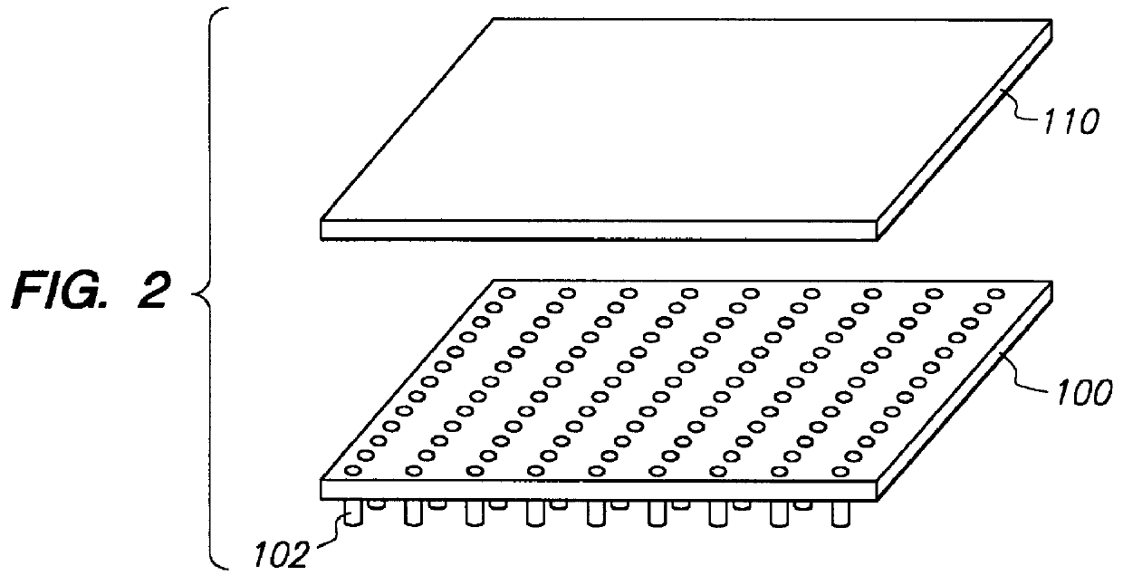
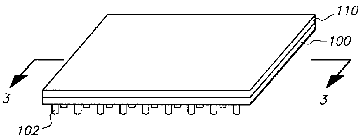
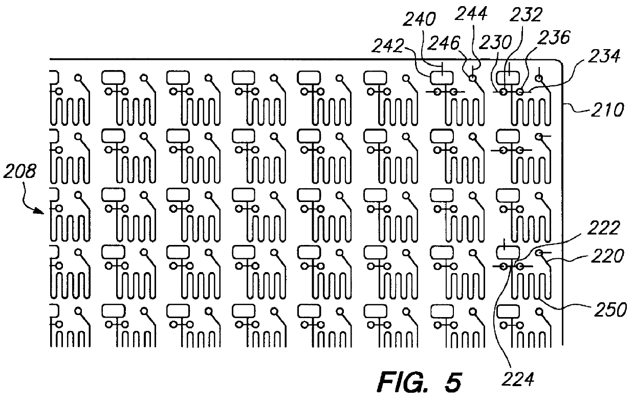
The present invention encompasses methods and apparatus for simultaneously transferring samples from an array of sample containers to an array of sample receiving elements, simultaneously transferring samples from said sample receiving elements to a planar array of microfluidic networks of interconnected cavity structures and channels of capillary dimensions and simultaneously conducting a microfluidic process. It is to be noted that simultaneous transfer may be from all or a portion of the array to a corresponding portion of the microfluidic networks. The miniaturized system of enrichment trenches, reaction chambers and detection zones enable multiple laboratory processes to be integrated "onboard" a planar substrate, including sample preparation, incubation, electrophoretic separations, and analyses.

The present invention differs from known procedures in microfluidic technology such as microelectrophoresis in that it provides for simultaneously sampling an array of samples; simulta...


PUM

PropertyMeasurementUnit
Capillary waveaaaaaaaaaa
Dimensionaaaaaaaaaa

Abstract

The present invention concerns an apparatus for conducting a microfluidic process. The apparatus comprises integral first and second plates. The first plate comprises an array of sample receiving elements for receiving a plurality of samples from an array of sample containers and dispensing the samples. The second plate comprises a planar array of microfluidic networks of cavity structures and channels for conducting a microfluidic process. Also disclosed is a method for processing an array of samples. At least a portion of each sample in an array of sample wells is simultaneously transferred to a corresponding array of microfluidic networks of cavity structures and channels by means of a corresponding array of sample receiving elements that is in integral fluid communication with the array of microfluidic networks. The samples are then processed. Also disclosed is a device for conducting a microfluidic process wherein the device comprising a planar substrate having a planar array of microfluidic networks of cavity structures and channels for conducting a microfluidic process. A plurality of such devices may be present on a continuous sheet. The invention further includes kits for carrying out microfluidic processes comprising an apparatus as described above.

Description

1. Field of the InventionThis invention relates generally to the receiving and dispensing of samples such as in the field of separation of biomolecules and, in particular, separations by capillary electrophoresis and the use of the capillary electrophoresis to detect such biomolecules.In a range of technology-based business sectors, including the chemical, bioscience, biomedical, and pharmaceutical industries, it has become increasingly desirable to develop capabilities for rapidly and reliably carrying out chemical and biochemical reactions in large numbers using small quantities of samples and reagents. Carrying out a massive screening program manually, for example, can be exceedingly time-consuming, and may be entirely impracticable where only a very small quantity of a key sample or component of the analysis is available, or where a component is very costly.Accordingly, considerable resources have been directed to developing methods for high-throughput chemical synthesis, screen...

Claims


Application Information

Patent Timeline
IPC IPC(8): B01L3/00B01J19/00G01N27/447G01N30/28G01N30/00G01N30/46G01N30/60G01N35/00B01L3/02C40B60/14
CPCB01J19/0046B01J19/0093B01L3/0268B01L3/5025B01L3/5027B01L3/50273G01N27/44743G01N27/44791B01J2219/00317B01J2219/00369B01J2219/00783B01J2219/00889B01J2219/00891B01L2200/10B01L2300/0829B01L2300/0838B01L2300/0883B01L2400/0406B01L2400/0415B01L2400/0421B01L2400/0442B01L2400/0481C40B60/14G01N30/466G01N30/6095G01N2030/285G01N2035/00237
Inventor BJORNSON, TORLEIF OVEMCCORMICK, RANDY M.SOANE, DAVID S.
Owner ACLARA BIOSCIENCES INC
Why Eureka
Try Eureka