Eureka AIR delivers breakthrough ideas for toughest innovation challenges, trusted by R&D personnel around the world.

Compositions and method for providing anisotropic conductive pathways and bonds between two sets of conductors

a technology of anisotropic conductive pathways and anisotropic conductive bonds, which is applied in the direction of printed circuit assembling, magnetic materials, metallic pattern materials, etc., can solve the problems of difficult to obtain particles, difficulty in conventional soldering, and high cost of particles

Inactive Publication Date: 2000-08-29
LOCTITE (R&D) LIMITED
View PDF75 Cites 48 Cited by
  • Summary
  • Abstract
  • Description
  • Claims
  • Application Information

AI Technical Summary

Benefits of technology

It is an object of the present invention to provide a composition and method for creating anisotropic conductive pathways utilising electrically-conductive particles which are readily available or which can be readily made.
It is a further object of the invention to provide a composition and a method which will create a regular structured pattern of anisotropic conductive pathways.
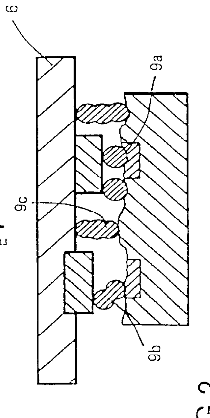
In one embodiment, the magnetic field is applied normal to the layer of the composition (i.e. in the Z direction) and the electrically-conductive particles form a regular array of particles in a monolayer or in columns, depending on the thickness of the layer. With a monolayer there is primarily single-particle bridging in the Z direction between the sets of conductors. The regular pattern improves the reliability of electrical contact. In a second embodiment the magnetic field is applied parallel to the layer of the composition (i.e. the X direction) and the electrically-conductive particles form parallel chains of particles, each in electrical contact with an adjacent particle or particles of the same chain. The chains are formed to lie parallel to the longitudinal axis of two sets of conductor pins or tracks. Here again, single-particle bridging in the Z-direction is achieved between the two sets of conductors but the particles are also in electrical contact with adjacent particles in the same chain so that reliability is further improved. In a case where two separate sets of conductor pins or tracks are located on opposite edges of an integrated circuit or other component, the layer of the composition will normally be interrupted at a central area of the component so that no conductive chain of particles extends across the width of the component to connect the two sets of conductors on the same component (unless in a special case this is desired). In the case of a "quad" component having conductor pins on four edges, with two sets at right angles to the other two sets, the layer of the composition is applied, exposed to the magnetic field and cured or activated in two steps, so that chains of conductive particles are formed in the X-direction and Y-direction with the appropriate alignments in the respective areas.
In the event that there are excursions from planarity in either the tracked substrate or in the level of each of the pin-outs (conductors) on the component to be bonded, the present invention allows for the formation of columns of conductive particles greater than one particle tall and this therefore offers the advantage of self adjustment with regard to bridging irregular gaps between substrates which require conductivity in the direction normal to the substrate plane.
The ferrofluids are effective insulators. The resistivity of a ferrofluid adhesive composition is likely to be further increased after curing.

Problems solved by technology

Conventional solder may give rise to difficulties because the solder may bridge the gap between two pins.
Such particles are expensive and difficult to obtain.
This is undesirable for interconnection in the electronics field, where the distribution of conductive pathways is critical in order to ensure conduction between each opposed pair of conductors.

Method used


Image

  • Compositions and method for providing anisotropic conductive pathways and bonds between two sets of conductors
  • Compositions and method for providing anisotropic conductive pathways and bonds between two sets of conductors
  • Compositions and method for providing anisotropic conductive pathways and bonds between two sets of conductors

Examples


example 1

Ferrofluid with Non-Magnetic Particles

The ordering of non-magnetic particles in a ferrofluid was first examined in accordance with the following experiment. A kerosene-based ferrofluid known as APG 511A was purchased from Advanced Products and Technologies Ltd., (Oxford, U.K.) which is a subsidiary of Ferrofluidics Corp., Nashua, N.H., USA. The characteristics of the fluid are indicated in Table 1.

To this fluid was added a qualitative concentration of monodisperse polymer beads (<0.5% w / w). The polymer beads were composed of polystyrene crosslinked to an extent of 55% with divinyl benzene (PS-DVB 55%). The beads coded Q496 were purchased from Dyno Particles AS, Lillestrom, Norway and had a mean diameter of 9.8 micrometers as measured with a Coulter (Trade Mark) LS Particles Size Analysis apparatus operating in the Fraunhofer optical mode.

A few drops of the dispersion of Q496 in APG 511A were placed on a microscope slide and subsequently covered with a coverslip. The continuous liqui...

example 2

Ferrofluid with Non-Magnetic Particles

In order to demonstrate that anisotropic structures could be locked in, albeit on a temporary basis, the following experiment was conducted. A sample was prepared in accordance with Example 1 except the distance between the coverslip and the microscope slide was set such that it corresponded to a dimension less than the diameter of two Q496 beads, i.e. <20 micrometers. In this arrangement it was not possible to align one bead directly on top of another as expected. Instead a tilted arrangement of spheres resulted such that two spheres became jammed between the substrate and the coverslip. When the magnetic field was removed this anisotropic tilted arrangement persisted indefinitely. The log-jammed structure indicates intimate bead-to-bead and substrate-to-bead contact, thus a connection between the upper substrate (coverslip) and the lower substrate has been realised by way of the included polymer beads. No such connection previously existed bec...

example 3

Ferrofluid with Non-Magnetic Fibre Particles

A composition such as described in Example 1 was made up except that chopped optical fiber was used in place of the Q496 beads. The fibers were nominally of 7.5 micrometer diameter and nominally 100 micrometers in length. The fibers were obtained from Sumita Optical Glass Inc., Tokyo, Japan and are of the type used in the control of cell thickness in liquid crystal display manufacture. Alignment of these rod-shaped non-magnetic inclusions by the means described in Examples 1 and 2 produced chains with increased contact areas between each chain element (individual fibers) as compared to the spherical beads of Examples 1 and 2.

Because there was a distribution of fiber lengths in the pure fiber sample there was a corresponding distribution of lengths in the fluid composition that contained said fibers. When such a sample was stimulated with a magnetic field normal to the substrate some fibers jammed between the upper and lower substrates whil...


PUM

PropertyMeasurementUnit
Temperatureaaaaaaaaaa
Magnetic fieldaaaaaaaaaa
Sizeaaaaaaaaaa

Abstract

The invention provides a composition (3) comprising: (i) a ferrofluid comprising a colloidal suspension (4) of ferromagnetic particles in a non-magnetic carrier liquid, and (ii) a plurality of electrically-conductive particles (5) having substantially uniform sizes and shapes, dispersed in the ferrofluid. Various types of substantially non-magnetic electrically-conductive particles (5) are described. Application of a substantially uniform magnetic field by magnet means (8) to the composition (3) causes the electrically-conductive particles (5) to form a regular pattern (9). The composition is used for providing anisotropic conductive pathways (9a, 9b) between two sets of conductors (2a, 2b; 7a, 7b) in the electronics industry. The composition may be a curable adhesive composition which bonds the conductors. Alternatively or in addition the electrically-conductive particles may have a latent adhesive property e.g. the particles may be solder particles. The ferrofluid may be a colloidal suspension of ferromagnetic particles in a liquid monomer.

Description

This invention relates to compositions and methods for providing anisotropic conductive pathways between two sets of conductors, and to compositions and to methods for making anisotropically-conductive bonds between two conductors. The invention is particularly for use in the electronics industry.Electronic components such as semiconductor chips are often very small and have minimal gaps between connectors such as pins. Conventional solder may give rise to difficulties because the solder may bridge the gap between two pins. Therefore anisotropically-conductive adhesives have been proposed for electrical interconnection. An anisotropically conductive adhesive (ACA) conducts electricity in one direction only (usually denoted as the Z direction) and should eliminate conduction in the plane perpendicular thereto (the X and Y directions).Various proposals for ACA's are reviewed by Ogunjimi et al. in Journal of Electronics Manufacturing (1992) 2, 109-118. They usually consist of an adhesi...

Claims


Application Information

Patent Timeline
IPC IPC(8): H01F41/14H01F1/44H01F41/16H01R4/04H01R4/00H05K3/32C09J5/06H05K1/09C09J9/02C09J11/04C09J201/00H01B1/00H01B1/20H01B5/00H01B5/16H01L21/60
CPCH01F1/44H01R4/04H05K3/323H01F41/16Y10T428/12069H01L2224/293H01R12/57H05K2201/0221H05K2201/023H05K2201/0233H05K2201/083H05K2203/104H01L2924/01019H01L2924/01079H01L2924/07811Y10T428/12347H01L2924/00H01F1/14
Inventor MCARDLE, CIARAN BERNARDBURKE, JOSEPH
Owner LOCTITE (R&D) LIMITED
Why Eureka
Eureka Blog
Learn More