Sealable chamber extrusion apparatus with seal controls

Inactive Publication Date: 2000-09-12
OWENS CORNING INTELLECTUAL CAPITAL LLC
View PDF31 Cites 21 Cited by
  • Summary
  • Abstract
  • Description
  • Claims
  • Application Information

AI Technical Summary

Benefits of technology

The hot melt exits the extruders on the machine or line axis, and the mixer-cooler is on that axis immediately downstream of the extruders. The mixer-cooler is a relatively axially short pressure vessel which has upstream and downstream tube sheets, between which extend closely spaced, relatively small mixing tubes, each of which may contain an axially continuous series of deflecting blades thoroughly to rotate and mix the melt, as individual static mixers. Connected to each tube sheet are heads which have large flaring conical chambers overlying the inlet and outlet ends of the large number or bundle of smaller mixing tubes. The heads provide an expanding and contracting flow path, without elbows, notches, niches or corners creating significant dead spaces which would adversely affect the melt. The inlet head has an inlet on the machine axis which is axially aligned with the outlet in th

Problems solved by technology

Such installations are costly and present many operating problems, particularly since the upper end of the chamber may be a number of meters above and a substantial distance from the lower end.
For sizable or complex extr

Method used


Image

  • Sealable chamber extrusion apparatus with seal controls
  • Sealable chamber extrusion apparatus with seal controls
  • Sealable chamber extrusion apparatus with seal controls

Examples


Example

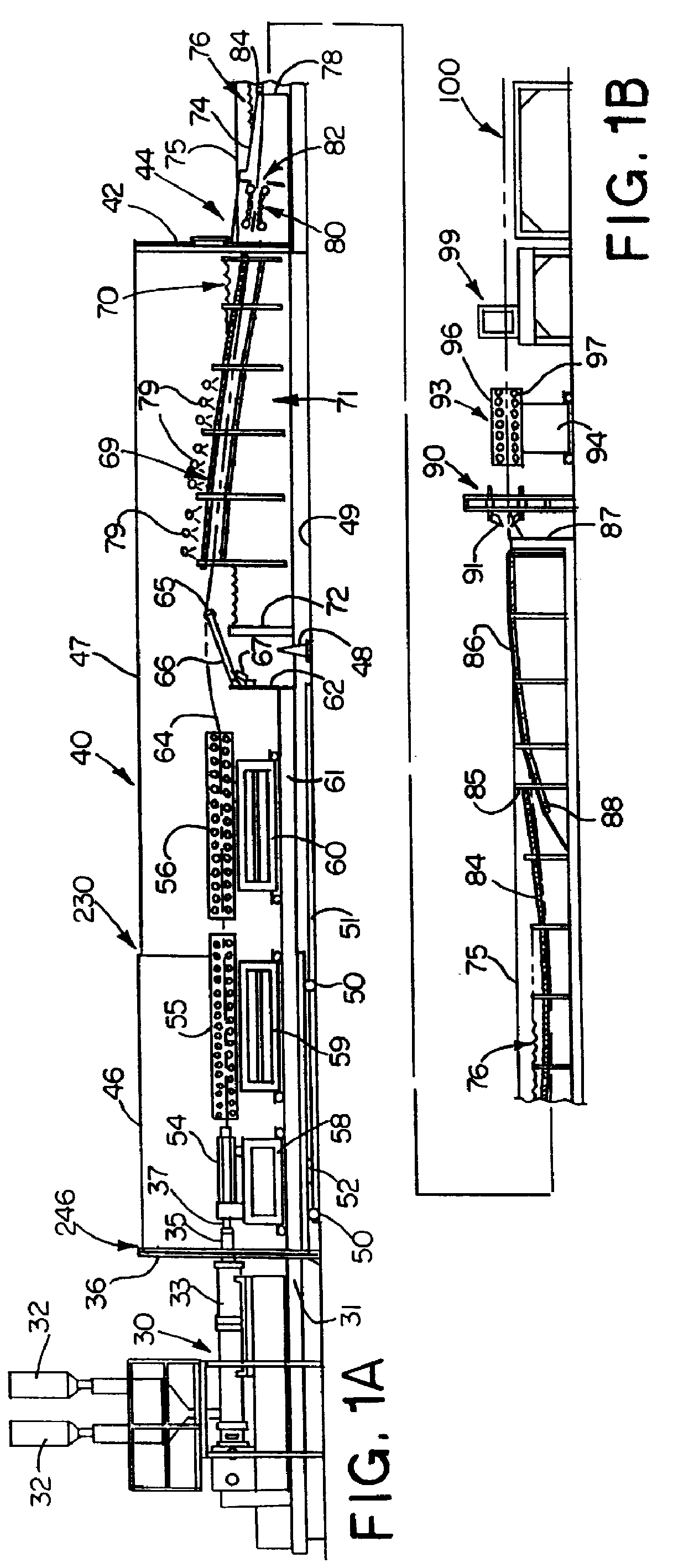
Referring now to the drawings and more particularly to FIGS. 1A and 1B, it will be seen that the extrusion line or system starts at the upstream end with an extruder 30. The extruder is mounted on stand 31 and includes hoppers 32 by which raw materials are fed to the extruder barrel 33 to be formed under heat and pressure into a foamable polymer melt.

An extension of the extruder indicated at 35 projects through a large diameter fixed bulkhead seen at 36. A die 37 is mounted on the end of the extruder extension within a chamber shown generally at 40. The fixed bulkhead 36 forms the upstream or entry end of the chamber 40. The downstream end is formed by a fixed bulkhead 42 and a water baffle seal is shown generally at 44. The seal permits the product to exit the chamber on a continuous basis.

In FIG. 1A, the chamber includes a movable section 46 which may telescope over the upstream end of fixed section 47. The fixed section is mounted on stanchions 48 on the floor 49, while the movab...


PUM

PropertyMeasurementUnit
Angleaaaaaaaaaa
Thicknessaaaaaaaaaa
Sizeaaaaaaaaaa

Abstract

An extrusion system utilizes single or tandem extruders and a mixer-cooler to extrude a foamable extrudate through a die in a sealable chamber. The foamable extrudate is shaped and calibrated within the chamber. The die is mounted on the end of a gel tube projecting through a gland seal in a fixed bulkhead forming the upstream end of the chamber. The gel tube and mixer-cooler are mounted on a movable carriage, movement of which may be used to adjust the die with respect to shaping and calibrating equipment inside the chamber. The mixer-cooler achieves a selected narrow range of uniform viscosity of the melt at the die depending on the size of the product and density. The chamber is preferably a vacuum chamber producing low density foams. The product exits the chamber to atmosphere on a continuous basis through a submerged orifice in a water baffle immersion seal. The mixer-cooler enables a large size low density product to be produced with uniform cellular structure without cell collapse or density gradients, as the product is subjected to the pressure and temperature transformations passing from the chamber to atmosphere through the water. The seal includes the submerged orifice with a free wheeling guiding system upstream of the orifice. Immediately ahead of the guiding system, the parameters of the foam extrudate are sensed to control the configuration of the orifice on a continuous basis. Before the extrudate passes into the water baffle seal it moves over a floating dancer roll, the position of which controls a haul-off such as a vacuum belt at the tail end of the system. This avoids pushing on the extrudate.

Description

DISCLOSUREThis invention relates generally to a sealable chamber extrusion apparatus and method with seal controls, and more particularly to an apparatus and method for forming high quality low density foam board at economical throughputs.Vacuum extrusion of high quality, low density polystyrene foam board sold under the well known color PINK.RTM. and FOAMULAR.RTM. trademarks by Owens Corning of Toledo, Ohio, USA, has been accomplished in inclined barometric leg vacuum extrusion lines. In such systems, the vacuum chamber is somewhat inclined. The die is positioned at the upper end along with shaping or calibration equipment. At the lower end, the chamber is closed by a hood extension and immersed in a pond of water. The pond seals the lower end of the chamber and provides an immersion cooling bath for the extrudate as it leaves the vacuum chamber. The buoyant extrudate may be supported beneath a continuously moving belt which moves through the pond through a large radius of curvatur...

Claims


Application Information

Patent Timeline
IPC IPC(8): B01J3/00B01J3/03B29C44/50B29C44/60B29C44/34B29C47/08B29C47/88B29C47/16B29C47/92B29C47/78B29C47/90B29C47/34B29C47/36B29C48/07B29C48/31B29C48/355B29C48/90B29C48/92
CPCB01J3/006B01J3/03B29C44/3403B29C44/3407B29C44/50B29C44/60B29C47/003B29C47/0808B29C47/165B29C47/34B29C47/362B29C47/78B29C47/884B29C47/90B29C47/905B29C47/92B29C47/0021B29C47/0026B29C47/904B29C2791/006B29C2947/92019B29C2947/92028B29C2947/92076B29C2947/92114B29C2947/92133B29C2947/92152B29C2947/92209B29C2947/92428B29C2947/92438B29C2947/92514B29C2947/92523B29C2947/92533B29C2947/92571B29C2947/9258B29C2947/9259B29C2947/92628B29C2947/92647B29C2947/92695B29C2947/92704B29C2947/92809B29C2947/92876B29C2947/92904B29C2947/92923B29C2947/92933B29C2947/92952B29C2947/92961B29K2105/04B29C44/505B29C48/92B29C2948/92209B29C2948/92704B29C2948/92876B29C48/07B29C48/08B29C48/09B29C48/10B29C48/12B29C48/254B29C48/313B29C48/355B29C48/362B29C48/832B29C48/87B29C48/913B29C48/9135B29C48/919B29C48/90B29C48/904B29C48/905B29C2948/92019B29C2948/92028B29C2948/92076B29C2948/92114B29C2948/92133B29C2948/92152B29C2948/92428B29C2948/92438B29C2948/92514B29C2948/92523B29C2948/92533B29C2948/92571B29C2948/9258B29C2948/9259B29C2948/92628B29C2948/92647B29C2948/92695B29C2948/92809B29C2948/92904B29C2948/92923B29C2948/92933B29C2948/92952B29C2948/92961B29B7/842B29B7/726B29B7/58B29C44/20
Inventor SADINSKI, ROBERT L.LINCOLN, JR., ROBERT M.WOODBURN, RUSSELL C.
Owner OWENS CORNING INTELLECTUAL CAPITAL LLC
Why Eureka
Try Eureka