Optical phase-change disc

a phase-change disc and optical storage media technology, applied in the direction of rewritable discs, optical recording/reproducing/erasing methods, instruments, etc., can solve the problems of limiting the number of times, increasing optically recognizable noise, and forming local defects of micron order siz

Inactive Publication Date: 2000-10-03
VERBATIM CORPORATION
View PDF16 Cites 80 Cited by
  • Summary
  • Abstract
  • Description
  • Claims
  • Application Information

AI Technical Summary

Problems solved by technology

For this reason, even if the recording layer is sandwiched by the dielectric protective layers, a repeated overwriting operation as many as several thousands or several tens of thousands times builds up a microscopic deformation or segregation in the recording layer, eventually leading to an increase of optically recognizable noise and the formation of local defects of micron order size.
This phenomenon, which limits the number of times for the overwriting operation, will present serious problem when the wobble is used in a disc having a high track density.
Such a file management area is a small limited region which is disposed along the innermost or outermost periphery of the entire recordable region of the optical disc, and remains to be less than several percents of the entire recordable region; a degradation attributable to the wobbled groove presents a problem mainly in the TOC region as far as the CD format is concerned.
Once an error occurs in this region, there results a failure to read data from the entire data area, and the disc can no longer be used, thereby limiting the life of the disc.
However, still there is a limit on the number of overwriting operations that can be used, and in addition, a procedure of the file management is troublesome, presenting a difficulty in the design for drives and device drivers.
In other words, the actual circumstance is that the number of overwriting operations which can be repeated for the entire disc is limited due to the presence of a region which is frequently rewritten and which occupies less than several percents.
The present inventors have found that a degradation resulting from a repeated overwriting operations is promoted in a CD-RW (rewritable compact disc) of phase-change type by the presence of the wobble, and noted that the degradation causes a more serious problem in the future when a higher track density is used.
The dielectric layer having a thickness below 10 nm may be insufficient to prevent a deformation of the substrate or recording layer as a protective layer.
If the thickness is above 500 nm, internal stresses within the dielectric layer itself and the differential elastic response with respect to the substrate become remarkable, tending to produce cracks.
Below a thickness of 70 nm, a microscopic deformation of the substrate is accumulated during the repeated overwriting operations, whereby a reproduced light is scattered causing a considerable increase of noise.
If the thickness of the lower protective layer is larger than 200 nm, the configuration of the groove as viewed in the plane of the recording layer will be changed, which is undesirable.
Specifically, the depth of the groove may become shallower than intended on the surface of the substrate, and the groove width may also be narrower than intended on the surface of the substrate, both of which are undesirable.
If the thickness is greater than 60 nm, there is a tendency that a microscopic plastic deformation is accumulated within the upper protective layer during the repeated overwriting operations, and this causes a reproduced light to be scattered, thereby increasing undesirable noise.
If the thickness of the recording layer is less than 10 nm, a sufficient contrast cannot be obtained, and there is also a tendency to retard the recrystallization rate, presenting a difficulty in erasing a record in a short time interval.
On the other hand, if the thickness exceeds 100 nm, an optical contrast is difficult to achieve, and a crack is likely to be produced, which is again undesirable.
In general, in the phase-change disc, microscopic deformation is accumulated in the protective layers or the surface of the substrate due to repeated overwriting operations, thereby scatters the focused optical beam to increase noise in the reproduced light or to change the thickness of the recording layer and protective layers, which retard accurate detection of the mark length.
The distortion of the groove geometry due to the overwriting operation applies to the groove wall.
The groove wall suffers from thermal damage due to the poor adherence to the thin film and stress concentration at the corner during the repeated overwriting operation.
If the groove width is too large, it leads to retard the tracking servo operation and reduce the density of tracks.
It was noticed that the degradation of the wobble resulted in the irregularity of the cyclic change of the envelope, which in turn resulted in larger noise leaked in the recorded signal.
On the other hand, an extremely smaller wobble amplitude does not provide a sufficient signal intensity for the wobble signal.
Such a protective effect (groove confinement effect) is not satisfactory for a groove depth below 25 nm.
On the other hand, for a groove depth which exceeds 200 nm, the adherence of a sputtered film to the groove wall becomes difficult, causing a reduced film thickness on the wall or a degraded film of a reduced density to be formed, which is undesirable.
Such an increased groove depth above 200 nm. is also undesirable in view of the difficulty of transferring the configuration of the groove by an injection molding technique.
In this instance, if a degradation due to the repeated overwriting operations occur, such information can no longer be retrieved correctly.
The drive may give rise to a delicate error in the position of the beginning or the end of the packet writing in view of the rising time of a laser or rotational jitter in drive system when a recording operation actually takes place by the modulation of the laser irradiation.
However, if such technique is established with CD-RW disc, the number of rewritings is expected to become enormous (for example, up to one hundred thousand to million times or more).
However, the proposed technique complicates the optical system and the signal processing system of the playback unit.
On the other hand, according to the investigation by us, it is found that the durability of the land against repeated overwriting operations depends on the relative relationship between the land width and the beam diameter, and when the land width becomes narrower than a specified value with respect to the beam diameter, a degradation proceeds rapidly.
However, when the land width is below the range described above, a failure in erasing the previous marks is remarkable during the repeated overwriting operation in the land, the jitter of recorded marks is degraded significantly.
It is noted that those of alloy metal layers mentioned above having compositions which permit a reversible change between crystal and amorphous states and which exhibit a reduced degree of cross-erase often have a melting point Tm below 700.degree. c and a crystallization temperature Tg equal to or above 150.degree. c. Tg below 150.degree. c makes the amorphous state unstable, thereby causing a cross-erase.

Method used


Image

  • Optical phase-change disc
  • Optical phase-change disc
  • Optical phase-change disc

Examples


embodiment 3

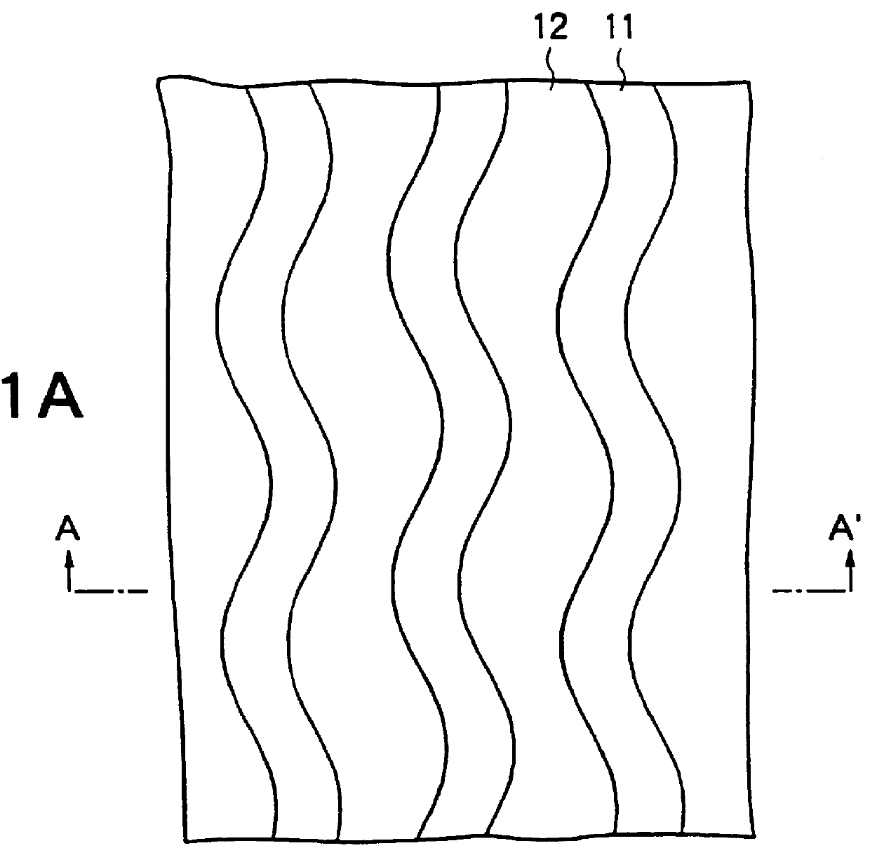
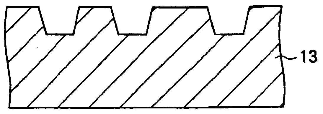
Formed in a polycarbonate substrate which was injection molded to a diameter of 120 nm and a thickness of 1.2 mm was a spiral groove having a pitch of 1.6 .mu.m, a width of about 0.5 .mu.m and a depth of about 40 nm. A wobble with a signal of 22.05 kHz was formed in the groove. The wobble was formed in four types having amplitudes of 27 nm, 20 nm, 13.5 nm and 0 nm (no-wobble).

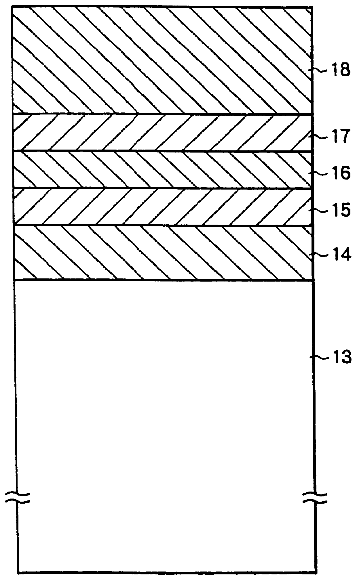
Sequentially laminated on the substrate were a lower protective layer of (ZnS).sub.80 (SiO.sub.2).sub.20 (mol %) to a thickness of 100 nm, a recording layer of Ag.sub.5 In.sub.6 Sb.sub.61 Te.sub.28 to a thickness of 20 nm, an upper protective layer of (ZnS).sub.80 (SiO).sub.20 to a thickness of 20 nm and finally a reflective layer of Al.sub.97.5 Ta.sub.2.5 to a thickness of 100 nm. Ultra-violet cured resin (SD318 manufactured by Dainippon Ink.) was coated on the resulting structure to a thickness of several .mu.m, thereby preparing a phase-change disc. A recording was made within the groove, forming amorphous m...

embodiment 4

A polycarbonate substrate having a spiral groove was prepared by injection molding. The refractive index at a wavelength of 680 nm was 1.56. Both the groove width and the land width were 0.75 .mu.m while the groove depth was about 70 nm. A lower dielectric protective layer, a recording layer, an upper dielectric protective layer and a reflective layer were sequentially formed on the substrate by sputtering.

Each of the lower and upper dielectric protective layer contained (ZnS).sub.80 (SiO.sub.2).sub.20, and had a thickness of 100 nm and 20 nm, respectively. A material for the recording layer contained as main components thereof Ge, Sb and Te, which were subjected to a reversible phase-change between amorphous and crystallized states in response to a laser irirradiation, and the composition of Ge:Sb:Te was in the atomic ratio of 2:2:5. The recording layer had a thickness of 25 nm. The reflective layer contained Al.sub.97.5 Ta.sub.2.5 deposited to a thickness of 100 nm. A ultra-violet...

embodiment 5

The same disc as used in the Embodiment 4 was rotated at a linear velocity of 15 m / s, and an arbitrary groove is chosen to record a signal having a frequency of 11 MHz by using the same recording apparatus as used in the Embodiment 4. A one-beam overwriting operation was performed with a recording power of 12 mW, and an erasing power and a bias power both of which were equal to 7 mW. C / N ratio was equal to 52 dB.

Subsequent to the recording operation, the recorded track was irradiated with DC laser irradiation having power of 7 mW, whereupon the carrier level was reduced by 25 dB, indicating a desirable erasability as represented by an erasure ratio of 25 dB. Subsequently, an arbitrary land was selected to make a similar record and a similar measurement of C / N ratio. It was found that C / N ratio was equal to 52 dB which is substantially same as in the groove. An erasure ratio in this instance was also equal to 24 dB, which was comparable to that obtained for the groove.


PUM

PropertyMeasurementUnit
depthaaaaaaaaaa
depthaaaaaaaaaa
thicknessaaaaaaaaaa

Abstract

An optical phase-change disc comprises a substrate having thereon a spiral groove or concentric grooves for guiding a focused light beam, and a layer structure including a recording layer and protective layers sandwiching therebetween the recording layer. The groove has wobble for recording ATIP (absolute time information) or ADIP (address information). The following relationship between the groove width GW, beam diameter R0 and wobble amplitude aw: 0.25< / =GW / R0< / =0.45 or 0.65< / =GW / R0; and 0.03< / =aw / GW< / =0.08 hold for preventing distortion of the groove caused by repeated overwriting operation to improve reliability of the optical disc.

Description

(a) Field of the InventionThe invention relates to a high density rewritable phase-change optical storage media, and more particularly, to a phase-change optical storage media which exhibits a reduced degradation during repeated overwriting.(b) Description of the Related ArtRecently, an increase in the amount of information data demands a high-density storage media which permits a recording / playback of a vast amount of information rapidly. It is expected that optical storage media would meet the need of such applications.An optical disc includes a write-once type which allows a recording operation only once and a rewritable type which allows an overwriting as many times as desired. A rewritable optical disc includes a magneto-optical disc which utilizes the magneto-optical effect and a phase-change disc which utilizes a change in the reflectivity associated with a reversible phase-transformation between crystallized and amorphous states. A phase-change disc does not require an exter...

Claims


Application Information

Patent Timeline
Patent Type & Authority Patents(United States)
IPC IPC(8): G11B27/24G11B27/19G11B7/24G11B7/007G11B27/30G11B7/00G11B7/0055G11B7/006G11B7/24079G11B7/24082
CPCG11B7/007G11B7/00718G11B7/24G11B7/24082G11B27/24G11B7/24079G11B7/00557G11B7/006G11B7/00745G11B2220/2545G11B27/3027G11B2220/216G11B2220/218
Inventor HORIE, MICHIKAZUOHNO, TAKASHIKUBO, HIDEYUKIKUBO, MASAEMIZUNO, HIRONOBUMIZUNO, MASAAKIKUNITOMO, HARUOTAKADA, KEN-ICHI
Owner VERBATIM CORPORATION
Why Eureka
Try Eureka