Cathode assembly, electron gun assembly, electron tube, heater, and method of manufacturing cathode assembly and electron gun assembly

a cathode and assembly technology, applied in the direction of discharge tube main electrodes, discharge tube/lamp details, discharge tube solid thermionic cathodes, etc., can solve the problems of size, resolution, cost, and existing heaters used in the conventional cathode assembly have reached their dimensions limits, etc., to achieve fast operation characteristics, reduce heater power, and reduce total length

Inactive Publication Date: 2000-10-10
TOSHIBA ELECTRON TUBE & DEVICES
View PDF26 Cites 35 Cited by
  • Summary
  • Abstract
  • Description
  • Claims
  • Application Information

AI Technical Summary

Benefits of technology

According to this arrangement of the present invention, there is provided an electron gun assembly which attains a great decrease in total length, a decrease in heater power, fast operation characteristics, and high precision in the space between the first grid and each cathode assembly.
The heater of the present invention comprises an insulating substrate consisting of boron nitride, a heating member consisting of a graphite and provided on the insulating substrate, and an electrode terminal joined to the heating member through a conductive layer. With this structure, the heating member can be e

Problems solved by technology

However, no flat display units have been developed, which can cope with electron tubes such as cathode ray tubes in terms of size, resolution, and cost.
However, the existing heaters used in the conventional cathode assemblies have reached their limits in terms of dimensions.
This causes a decrease in temperature rise rate.
In the cathode assembly having the above structure, however, heat conduction to the sleeve cannot be prevented.
In this case, however, problems are posed in terms of thermal distortion of the cathode itself; limitations are imposed on the application of this method.
The following problems are posed when such a conventional electron tube is used for a low-profile display unit.
The total length of the electron gun assembly is too long.
The heater power required for the cathode assembly in the conventional electron gun assembly is not sufficiently low.
If, for example, conventional electron gun assemblies are used, the total heater power becomes 0.35 W.times.24 (assemblies)=8.4 W, posing a problem in terms of power saving in the electron tube.
In addition, in an electron tube having a plurality of electron gun assemblies, if the fast operation characteristics of the cathode assemblies of the respective electron gun assemblies vary, the overall image displayed on the display unit after the power is turned on is disturbed.
In a conventional electron gun assembly, however, it takes 10 seconds to obtain a stable image.
This rise time is too long to

Method used


Image

  • Cathode assembly, electron gun assembly, electron tube, heater, and method of manufacturing cathode assembly and electron gun assembly
  • Cathode assembly, electron gun assembly, electron tube, heater, and method of manufacturing cathode assembly and electron gun assembly
  • Cathode assembly, electron gun assembly, electron tube, heater, and method of manufacturing cathode assembly and electron gun assembly

Examples


first embodiment

An electron tube according to the present invention will be described below with reference to the accompanying drawing.

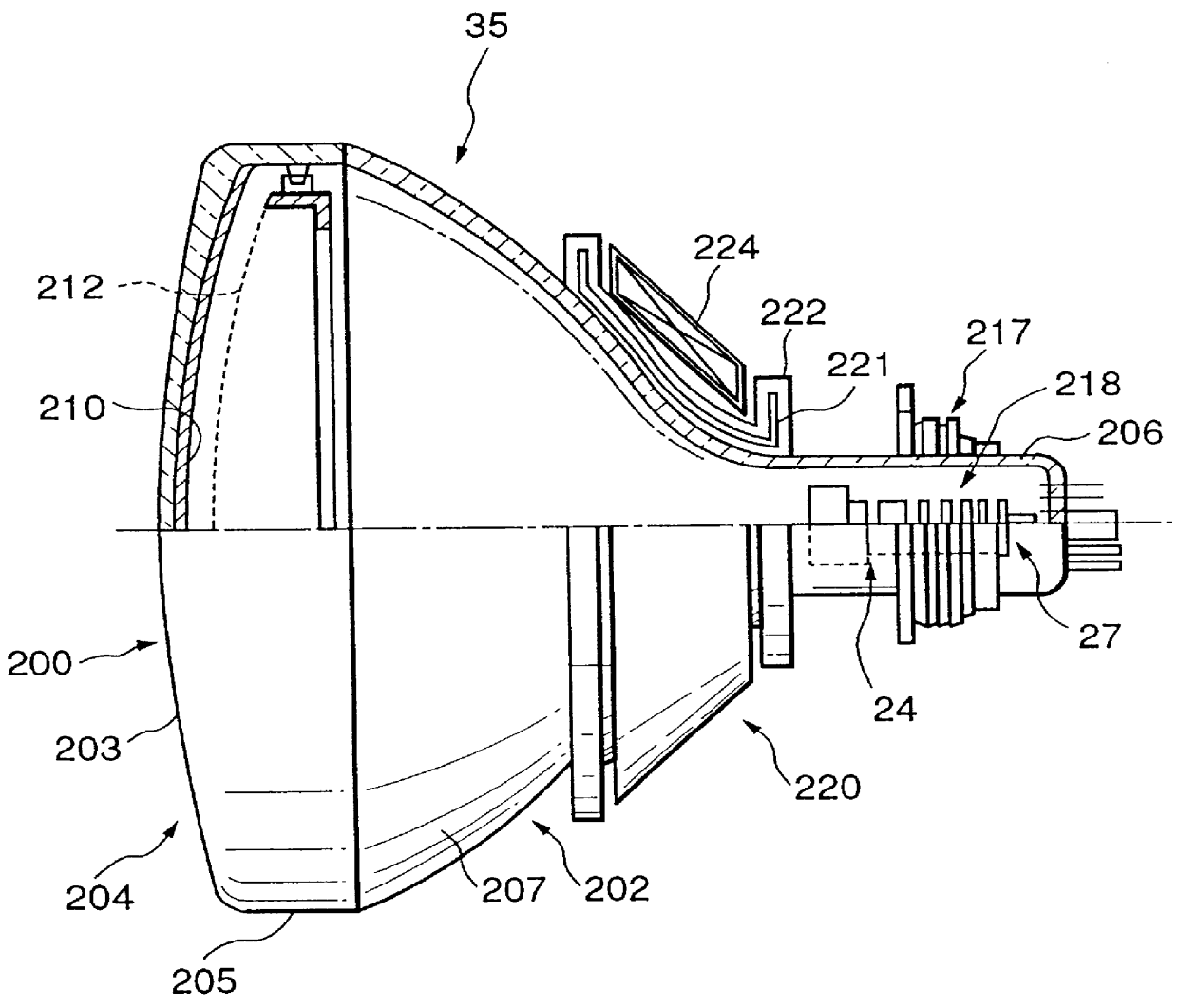
As shown in FIG. 1, an electron tube 35 includes a vacuum envelope 204 having a face panel 200 formed of glass and a funnel 202 joined to the face panel 200. The face panel 200 has a substantially rectangular effective portion 203 and a skirt portion 205 extends upright from the periphery of the effective portion 203. The funnel 202 has a cylindrical neck 206 at one end portion thereof, and a substantially rectangular, large-diameter cone portion 207 at the other end portion. The cone portion 207 corresponds to the outer shape of the skirt portion 205 of the face panel 200. The funnel 202 has a funnel-like shape as a whole. The cone portion 207 is joined to the face panel 200.

A phosphor screen 210 having of phosphor layers of three colors which emit blue, green, and red light beams is formed on the inner surface of the effective portion 203 of the face panel 200. A ...

fifth embodiment

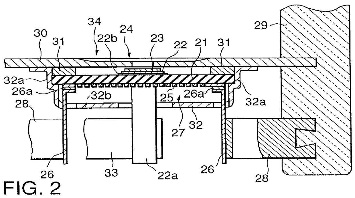
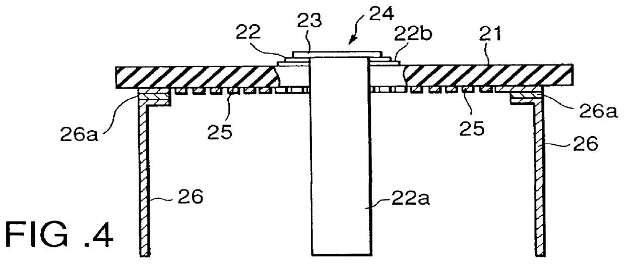
FIG. 16 shows the cathode assembly of an electron tube according to the present invention. A cathode assembly 27 has an insulating substrate 21 consisting of APBN and having a pair of opposing surfaces. An APG heating member 25 with a zigzag pattern is formed on one surface of the insulating substrate 21. Heater electrode terminals 26, each consisting of a tungsten wire or the like, are joined to the two end portions of the heating member 25 through metal layers 26a consisting of titanium or the like.

A cathode base member 24 is formed on the other surface of the insulating substrate 21. The cathode base member 24 is constituted by a base metal layer 22 consisting of a nickel (Ni) powder doped with magnesium (Mg) and silicon (Si), which are reducing agents, in small amounts, and formed on the entire surface of the insulating substrate 21, and an emissive material 23 with which the base metal layer 22 is coated or impregnated. In this embodiment, the base metal layer 22 is formed on t...

third embodiment

According to this embodiment having the above structure, since the electron gun assembly 34 is constituted by a combination of the three cathode base members 24, each having the same effects as those in the third embodiment, and the grid 30, a compact, high-performance electron gun assembly and color cathode ray tube can be obtained.


PUM


Abstract

PCT No. PCT/JP97/01706 Sec. 371 Date Jan. 16, 1998 Sec. 102(e) Date Jan. 16, 1998 PCT Filed May 21, 1997 PCT Pub. No. WO97/44803 PCT Pub. Date Nov. 27, 1997A cathode assembly (27) includes a thermally conductive insulating substrate (21) having a pair of opposing surfaces. A cathode base member (24) is formed on one surface of the insulating substrate, and a heating member (25) for heating the cathode base member is formed on the other surface of the insulating substrate. A heater electrode terminal (26) is fixed to the electrode of the heating member through a metal layer (26a). A first grid (30) is fixed to the insulating substrate to oppose the cathode base member through a predetermined space.

Description

The present invention relates to a cathode assembly, an electron gun assembly, an electron tube, and a heater which are used for the electron guns of a color cathode ray tube, and a method of manufacturing the cathode assembly.Recently, downsizing has been required for display units used for computers. With the widespread use of personal computers, in particular, a great deal of attention has been paid to flat displays, mainly liquid crystal displays. However, no flat display units have been developed, which can cope with electron tubes such as cathode ray tubes in terms of size, resolution, and cost. For this reason, electron tubes such as cathode ray tubes are in urgent need of reducing their total lengths and weights.Similar needs are increasing with respect to traveling wave tubes designed to be mounted in satellites. With such needs, demands have arisen for compact, low-profile, lightweight electron guns including cathode assemblies as tube parts.High-speed operations are often...

Claims


Application Information

Patent Timeline
IPC IPC(8): H01J29/48H01J29/04H01J1/20H01J1/22H01J1/24H01J9/04
CPCH01J1/22H01J1/24H01J9/04H01J29/485H01J29/04H01J2231/1255H01J2201/2878
Inventor KOBAYASHI, KAZUOSUDO, TAKASHIHIGUCHI, TOSHIHARUTAKAHASHI, HIDEHARUKIMURA, SAKAEKOSHIGOE, SHINPEIFUJIUCHI, TAKUMI
Owner TOSHIBA ELECTRON TUBE & DEVICES
Why Eureka
Try Eureka