Wide bandwidth, current sharing, Mosfet audio power amplifier with multiple feedback loops

a technology of mosfet audio power amplifier and feedback loop, which is applied in the direction of push-pull amplifiers, single-ended push-pull amplifiers, phase splitters, etc., can solve the problems of small gate voltage changes, virtually unaffected bandwidth, and difficult to establish a quiescent bias point using traditional techniques

Inactive Publication Date: 2000-11-07
BARBETTA ANTHONY T
View PDF1 Cites 14 Cited by
  • Summary
  • Abstract
  • Description
  • Claims
  • Application Information

AI Technical Summary

Problems solved by technology

First, when driving the MOSFET devices in the linear region, only small changes in gate voltage are necessary to command large changes in drain/source current.
Second, bandwidth is virtually un-affected because the typical 100 ohm resistor commonly used as a gate isolation device and which forms a low pass filter with the device capacitance, typically has a pole at several megahertz, which is well above any recognized bandwidth of interest with regard to audio applications.
One of the fundamental disadvantages of MOSFET devices is that they exhibit a wide variation in gate threshold voltage among individual devices having the same part number, and a temperature coefficient of gate threshold that does not relate to bi-polar transistors, which makes it difficult to establish a quiescent bias point using traditional techniques.
In established topologies, the feedback connection is not sufficient to fully remove this error component from the audio output, which makes a certain amount of conduction overlap imperative.
Audio power stages with very large conduction overlap, such as class A amplifiers, are considered to have very low audible distortion but achieve this at the expense of very high power dissipation.
Quiescent level power dissipation generates an undesirable temperature rise in the transistor heatsink.
In MOSFET devices there is also a lack of correlation between initial threshold voltage and linear transconductance, which makes them extremely difficult to match by selection of devices from a large batch of supposedly identical devices.
This is a costly process, and in order to compensate for changes in matching of device characteristics with component ag

Method used


Image

  • Wide bandwidth, current sharing, Mosfet audio power amplifier with multiple feedback loops
  • Wide bandwidth, current sharing, Mosfet audio power amplifier with multiple feedback loops
  • Wide bandwidth, current sharing, Mosfet audio power amplifier with multiple feedback loops

Examples


Embodiment Construction

Those of ordinary skill in the art will realize that the following description of the present invention is illustrative only and not in any way limiting. Other embodiments of the invention will readily suggest themselves to such skilled persons.

In the disclosure presented herein, MOSFET devices disclosed herein include at least single transistor devices, such as MTP 12 N 20, MTP 12 P 20, available from sources such as Motorola Semiconductor of Phoenix Ariz., and single or multiple transistor functional equivalents thereof, whether now known or unknown.

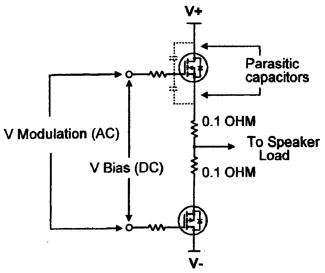
FIG. 1 is a schematic diagram which shows a typical prior-art output stage of a MOSFET audio power amplifier. The amplifier of FIG. 1 suffers from the aforementioned drawbacks relating to transistor matching problems.

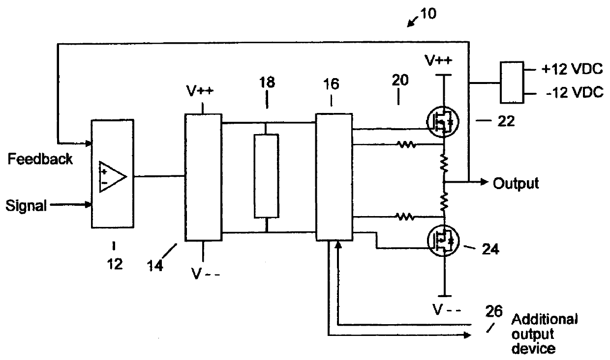
Referring now to FIG. 2, a diagram of an amplifier 10 is presented which can employ MOSFET transistors in the voltage gain and current gain stages. The amplifier 10 of FIG. 2 employs unique modulating techniques disclosed ...


PUM


Abstract

A wide bandwidth, multi-FET current sharing output stage, MOS audio power amplifier employs multiple feedback loops. An audio input is supplied to a voltage feedback amplifier stage driving a push-pull voltage gain/phase splitter stage. A bias adjustment stage driven from the push-pull voltage gain/phase splitter stage drives a current drive stage. The current drive stage drives an output stage comprising a plurality of paralleled current shared individual MOS output transistors driving an output node connected to a load. Up to three feedback loops are employed. A first voltage feedback loop comprises a voltage feedback stage having an input connected to a voltage divider driven from the first terminal of the load and an output connected to a feedback input node in the voltage feedback amplifier stage. A second voltage feedback loop comprises a voltage feedback stage having an input connected to the first terminal of the load and an output connected to a feedback input node in the push-pull voltage gain/phase splitter stage. A third feedback loop comprises a current feedback stage having an input in series between the output node and the load and an output connected to a feedback input node in the voltage feedback amplifier stage. The current feedback connection works in conjunction with input stage to lower distortion and provide a relatively flat frequency response.

Description

1. Field of the InventionThe present invention pertains to audio amplifiers. More particularly, the present invention pertains to wide bandwidth, current sharing, mosfet audio power amplifier with multiple feedback loops.2. The Prior ArtMOSFET transistors have a number of advantages when used in audio power output stages. The complementary push-pull source follower stage such as is typically employed in such applications is essentially a voltage operated current output device with extremely high input impedance, thus requiring very small drive currents in the micro-ampere range. These small drive currents are well within the output capability of low level linear circuits such as monolithic operational amplifiers.Such MOSFET transistors are extremely stable in the source follower connection because they have a voltage gain of less than unity. Further, they are easily driven to the power supply rails using traditional capacitor bootstrap techniques, and they perform well in releasing ...

Claims


Application Information

Patent Timeline
IPC IPC(8): H03F1/08H03F1/34H03F3/26H03F3/30
CPCH03F1/086H03F1/342H03F3/3018H03F3/3001H03F3/265
Inventor BARBETTA, ANTHONY T.
Owner BARBETTA ANTHONY T
Why Eureka
Try Eureka