Ballast circuit for high intensity discharge lamps

a discharge lamp and ballast circuit technology, applied in the direction of electric variable regulation, process and machine control, instruments, etc., can solve the problems of high power loss in heat, light flickering, and add to the cost of producing these circuits, so as to minimize current levels being manipulated, eliminate flickering, and eliminate flicker

Inactive Publication Date: 2001-01-30
EXCELITAS TECH
View PDF7 Cites 115 Cited by
  • Summary
  • Abstract
  • Description
  • Claims
  • Application Information

AI Technical Summary

Benefits of technology

It is a further object of the present invention to provide such a ballast circuit which may be produced using standard, inexpensive components.
It is a further object of the present invention to provide such a ballast circuit which eliminates flickering induced by high frequencies.
It is a further object of the present invention to provide such a ballast circuit which produces a steady output to eliminate flickering.
The invention results from the realization that a smaller, more compact and more efficient ballast circuit for a high intensity discharge lamp can be achieved by initialling boosting the input voltage to a higher level, thereby reducing the current to a proportionally lower level then flirter tailoring the voltage for the transition to the steady state mode of operation of the discharge lamp to minimize current levels being manipulated, to reduce power losses to heat, and reduce the number of components required and their complexity, and then bucking the voltage back down to the lower voltage and proportionally higher current required for operating the lamp.
In a preferred embodiment, the boost converter may include an inverter, responsive to the dc input, for producing an ac output. The boost converter may include a step-up transformer, responsive to the ac output, for producing a boosted, alternating output. The boost converter may include a rectifier, responsive to the boosted, alternating output, for producing the boosted dc output voltage. The buck controller may include a variable pulse width generator, responsive to the boosted dc output voltage, for providing a pulsed, reduced voltage output. The boost converter may include a resonant voltage divider, responsive to the reduced, pulsed output, for producing the reduced output voltage. The buck converter may include an output filter, responsive to the reduced output voltage, for eliminating ripple current, limiting electromagnetic interference, and reducing flicker of the discharge lamp. The output filter may be incorporated into the resonant voltage divider. There may be an voltage over protection circuit, responsive to a voltage differential between the reduced dc output voltage and the voltage at the lamp, for preventing the variable pulse width generator from producing the high voltage, pulsed output. There may be an ignitor, responsive to said boosted output, for igniting a high intensity discharge lamp. There may be an input filter, responsive to the dc input voltage for eliminating noise from the dc input voltage.

Problems solved by technology

However, because these circuits operate at higher currents, the circuits must include heavy duty components specially designed to carry such high currents which further adds to the expense of producing these circuits.
Moreover, because the ac voltages include high frequencies, the circuits must protect against acoustic arc resonance induced by the high frequencies which further causes the light to flicker.
By requiring numerous and complex circuits to accommodate the above requirements, there is a high power loss in the form of heat due to the high current through so many different circuits.
This further requires a means for cooling the circuit by a cooling interval before relighting the lamp as well as the need for actively cooling the circuits by including fans, further adding to the current consumed by the circuit to operate the fans and further increasing the power losses.
As a result, these lamps are neither energy efficient nor inexpensive to produce and operate.

Method used


Image

  • Ballast circuit for high intensity discharge lamps
  • Ballast circuit for high intensity discharge lamps
  • Ballast circuit for high intensity discharge lamps

Examples


Embodiment Construction

Other objects, features and advantages will occur to those skilled in the art from the following description of a preferred embodiment and the accompanying drawings, in which:

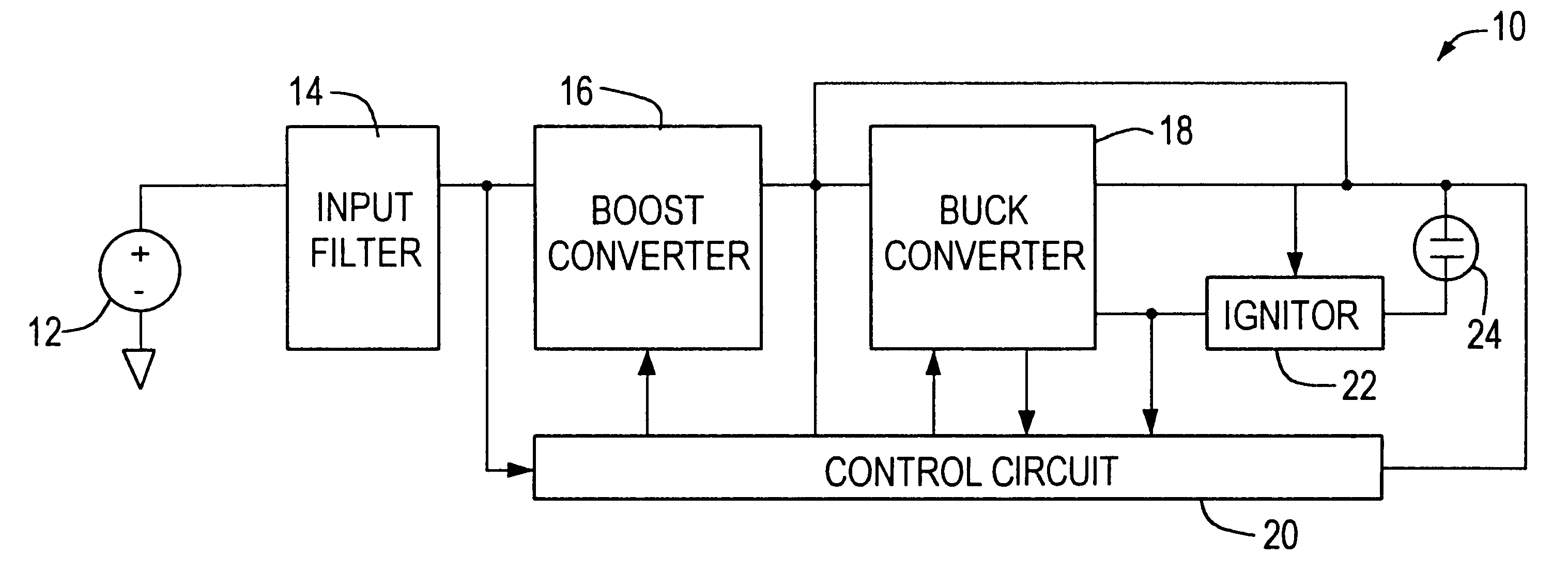
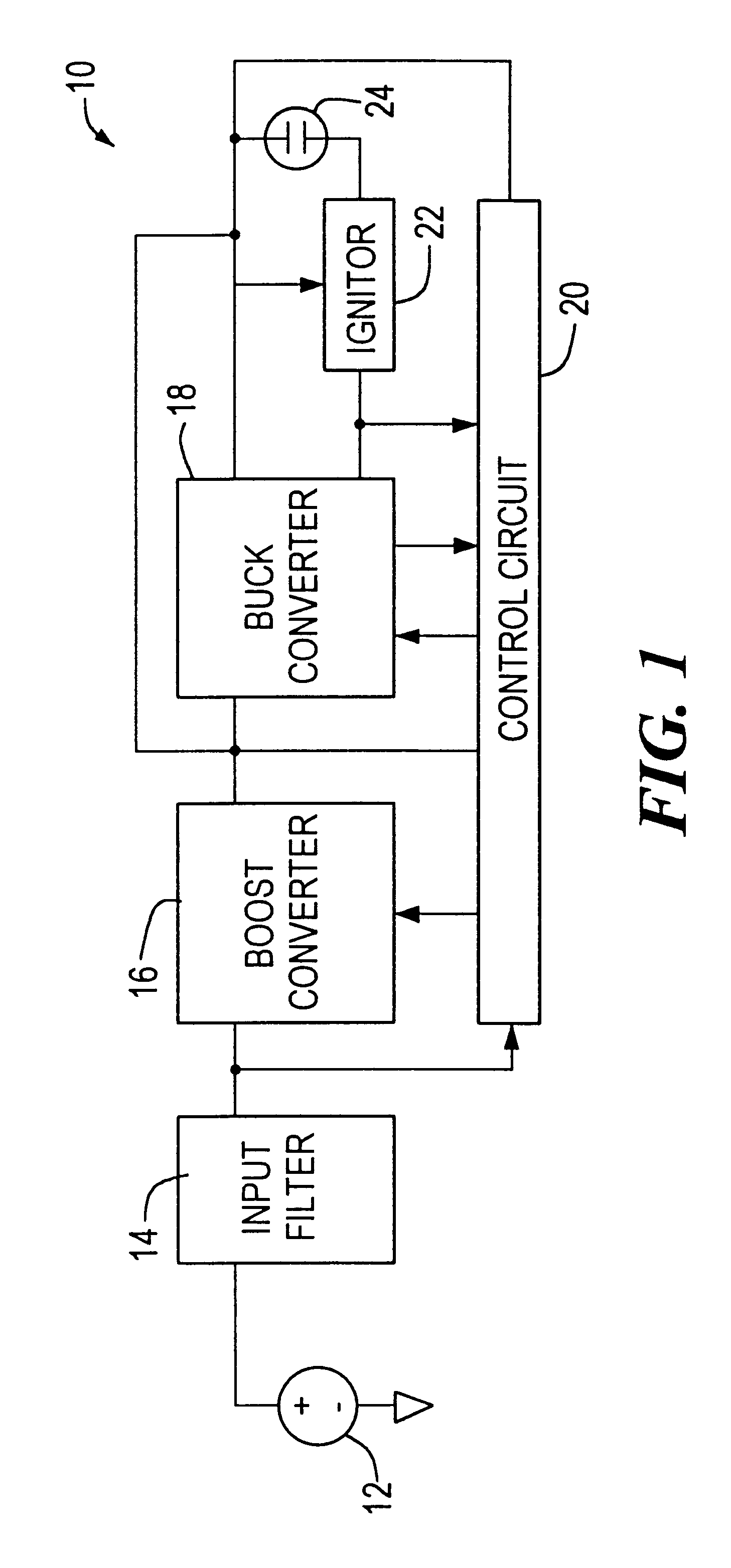
FIG. 1 is a schematic block diagram of a high intensity discharge lamp system including the ballast circuit of the present invention comprising a boost converter circuit, a buck converter circuit and a controller circuit;

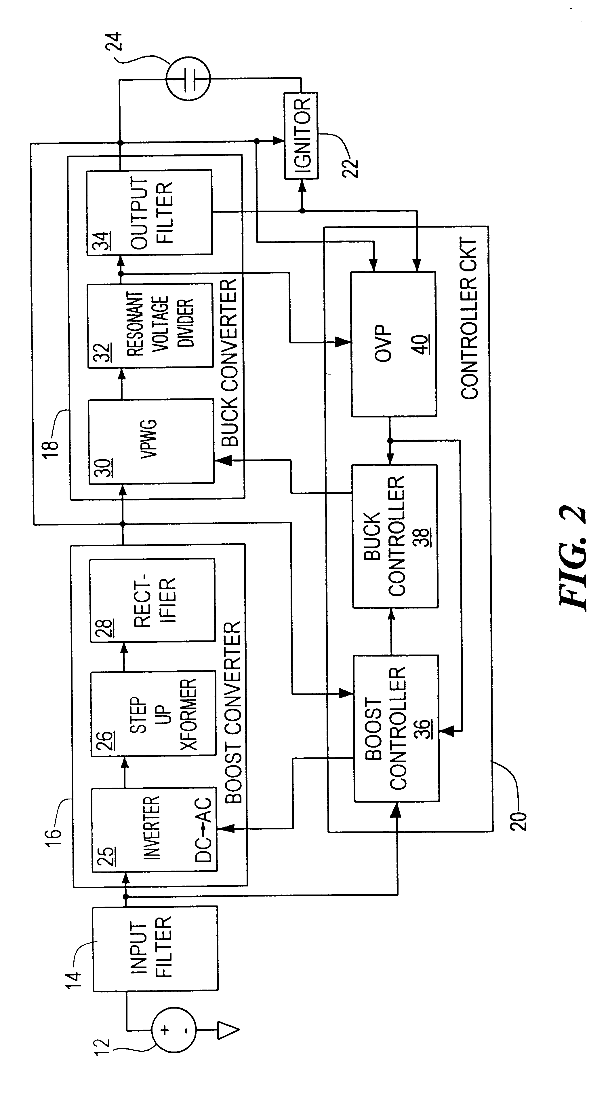
FIG. 2 is a more detailed schematic block diagram of FIG. 1 in which the boost converter, buck converter and controller circuits are further broken down into respective component circuits;

FIG. 3 is a schematic diagram of a boost converter and a portion of the controller circuit according to the present invention;

FIG. 4A is a schematic diagram of a trigger circuit used to ignite a high intensity discharge lamp having an ignition voltage of less than 10 KV;

FIG. 4B is a schematic diagram of a trigger circuit, similar to FIG. 4A, used to ignite a high intensity discharge lamp having an ignition vol...


PUM


Abstract

A ballast circuit for a high intensity discharge lamp includes a boost converter, responsive to a dc input voltage, for providing a boosted dc output voltage; a boost controller, responsive to the boosted dc output voltage, for driving the boost converter to maintain the boosted output voltage at a predetermined level; a buck converter, responsive to the boosted dc output voltage, for providing a reduced dc output voltage; and a buck controller, responsive to the reduced output voltage, for driving the buck converter to operate the discharge lamp in a transition mode and maintaining the reduced dc output voltage at a preselected level for operating the discharge lamp in a steady state mode.

Description

This invention relates to high intensity discharge lamps, and more particular, to a ballast circuit for a high intensity discharge lamp which is more efficient and requires fewer components than previous ballast circuits.BACKGROUND OF INVENTIONHigh intensity discharge (HID) lamps provide light by producing an arc between an anode and a cathode, rather than energizing a filament. These lamps include dc metal halide lamps and high pressure Xenon lamps which combine high luminance and good color retention. Applications include low dc input, portable light fixtures and ac powered fiber-optic illuminators used for industrial and medical lighting.Typical ballast circuits take a low input, ac or dc, and amplify the input over several stages producing high currents and thus requiring circuits which can control the current to provide a more steady current thereby providing a more steady light output, i.e. no flickering of the light. However, because these circuits operate at higher currents,...

Claims


Application Information

Patent Timeline
Patent Type & Authority Patents(United States)
IPC IPC(8): H05B41/28H05B41/288H05B41/292H05B41/282
CPCH05B41/2881H05B41/2885H05B41/2886H05B41/2925Y02B20/202Y10S315/05Y02B20/00
Inventor LAU, LAKE
Owner EXCELITAS TECH
Why Eureka
Try Eureka