

Apparatus and method for purification of agricultural animal waste
- Summary
- Abstract
- Description
- Claims
- Application Information
AI Technical Summary
Benefits of technology
Problems solved by technology
Method used
Image

Examples
first embodiment
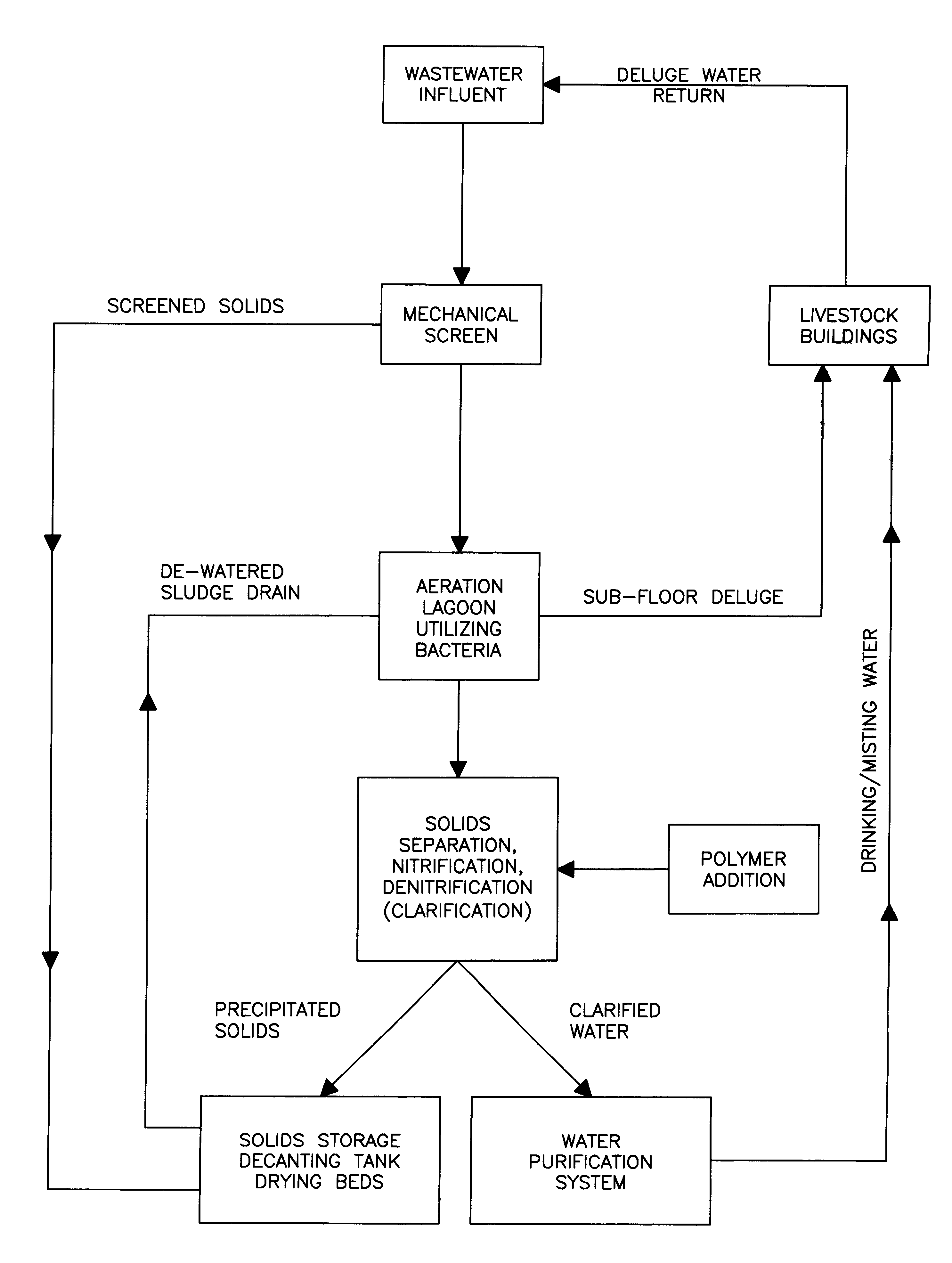
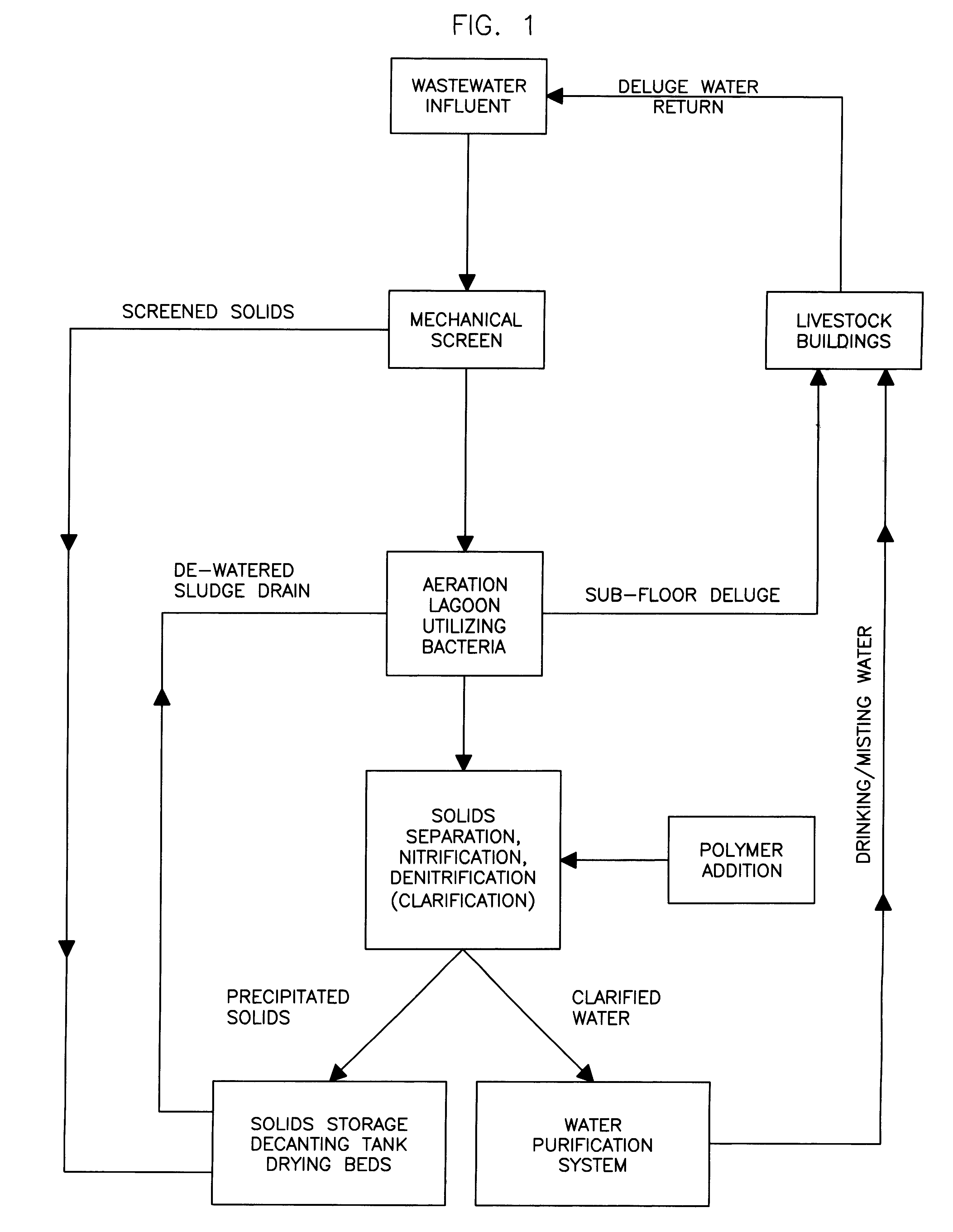
the present invention is based upon a multiphase approach including aerobic treatment in an aerobic lagoon with mechanical aeration, solids separation and nitrification / denitrification in an oxic / anoxic environment and disinfection of water through use of ozone. It is well within the skill of one in the art to vary the size of individual components and retention times based upon the parameters and amount of the agricultural wastewater.
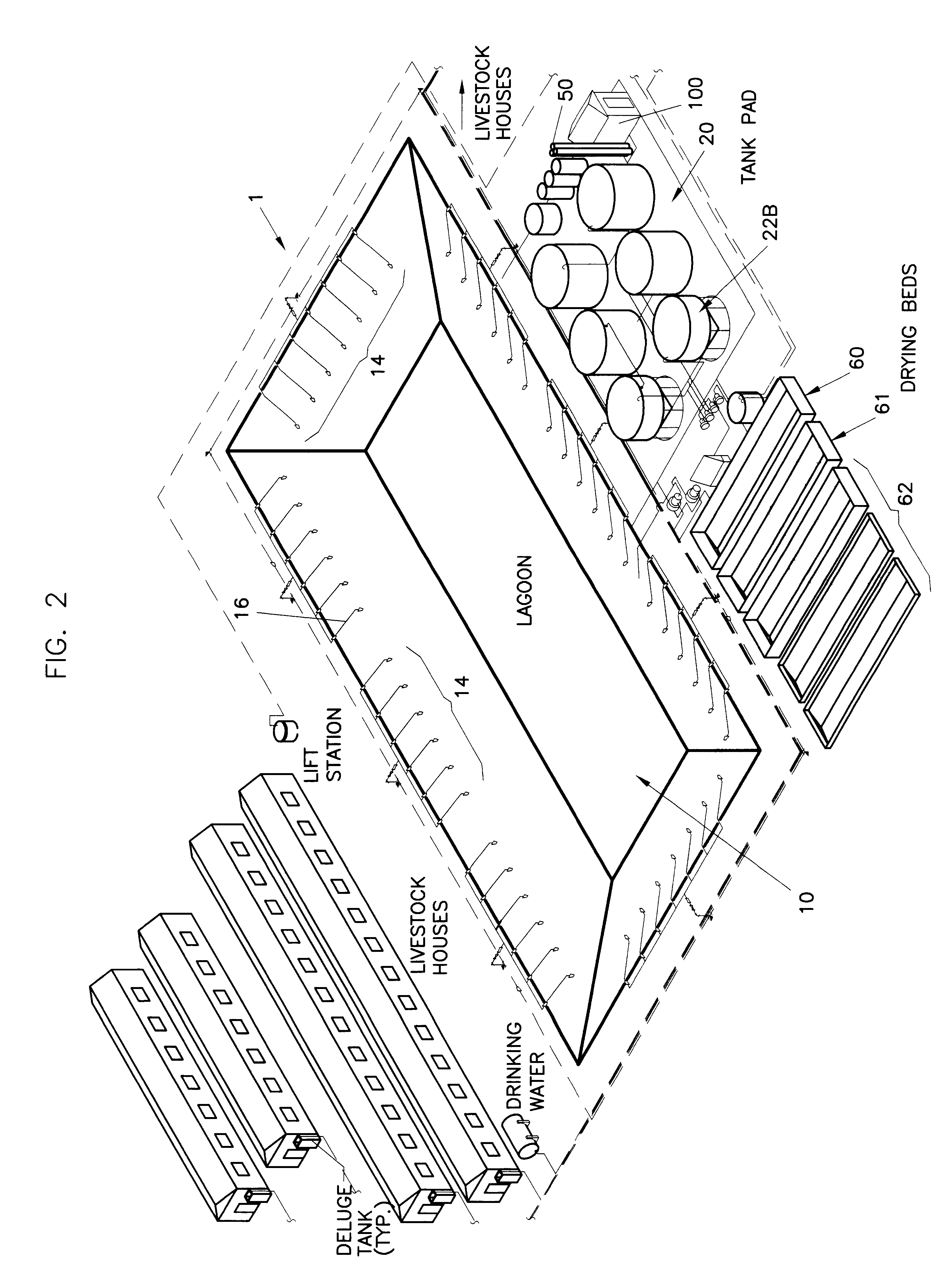
FIGS. 2-4 illustrate new installation / constructions in which a custom apparatus and system is designed for a specific agricultural operation. However, based upon the teachings of the present invention, it is within the skill of one in the art to retrofit existing agricultural facilities with equipment for treating the wastes modifying existing piping and lagoons to accomplish the proposed treatment scheme.
The wastewater purification system 1 of the present invention comprises an aerobic lagoon 10 wherein the primary treatment occurs based upon a combin...
second embodiment
The second embodiment incorporates a means for controlling nutrient levels that are applied to cropland via spray irrigation from the various stages of treatment. This capability enables an operator to obtain wastewater for irrigation at specific nutrient levels based on residual concentrations during the various phases of treatment. In a pilot study, contamination reduction values were observed for the treatment system (based upon only the aerobic and anoxic phases of treatment):
It is expected that contamination reductions in practical use at an agricultural facility will meet or exceed those observed during pilot testing once bacterial populations become established and the system reaches steady state. Polymer addition will precipitate even more phosphorus and various micro-nutrients from the effluent as required by the user.
Because typical anaerobic treatment is not meeting the effluent requirements for many dairies the alternative option is a "municipal" treatment facility. Muni...
PUM
| Property | Measurement | Unit |
|---|---|---|
| Time | aaaaa | aaaaa |
| Fraction | aaaaa | aaaaa |
| Fraction | aaaaa | aaaaa |
Abstract
Description
Claims
Application Information