Ocean thermal gradient hydraulic power plant

Inactive Publication Date: 2001-03-20
BECK EARL J
View PDF8 Cites 23 Cited by
  • Summary
  • Abstract
  • Description
  • Claims
  • Application Information

AI Technical Summary

Benefits of technology

Just so in the future development of an OTHGHPP we may anticipate future improvements in system design on certain factors now understood but not fully appreciated in terms of power plant design. These do not relate to factors that promise to improve cycle efficiency per se. As the OTGHPP does not depend on expansion of the steam in the bubble reducing density in the SLP, they rather relate to two variables that will effect the output of a plant of a given size. First there is the immersion of the SLP's intake S below sea level. As S is increased beyond the minimm to insure continuous intake of warm seawater, say 1 or 2 m, the pressure at the entry of the CCN increases and since the pressure at its outlet is related to the water temperature, that is not a major variable. If we have a water of a certain temperature, say 27.degree. C., then to make steam bubbles of a desired size, we must lower the pressure in the SLP sufficiently below the saturation pressure to maintain that bubble size. When the submergence S is increased and the pressure at the SLP's intake increased, the pressure drop across the CCN wil 1 increase and so the velocity of the water at its outlet. 
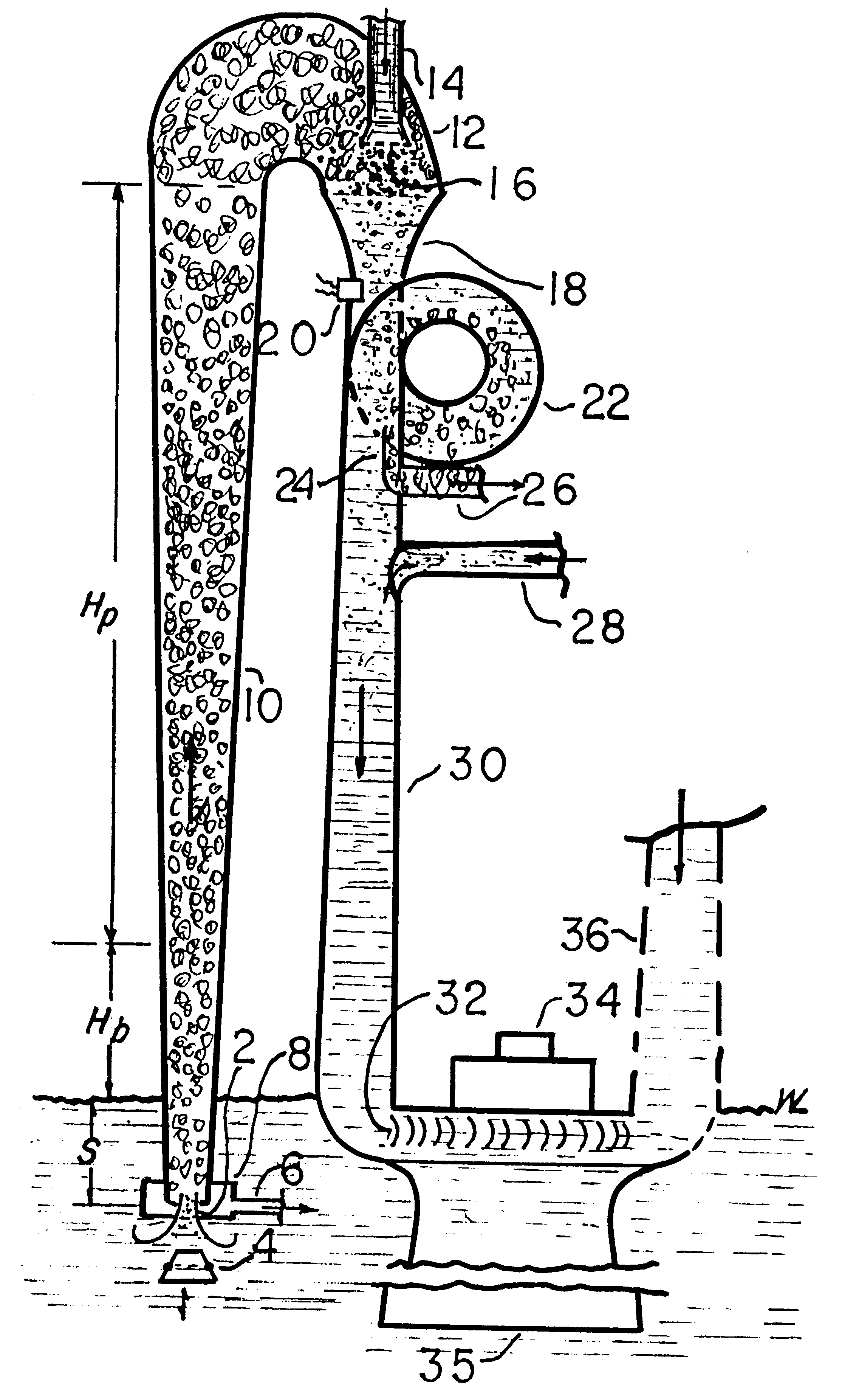
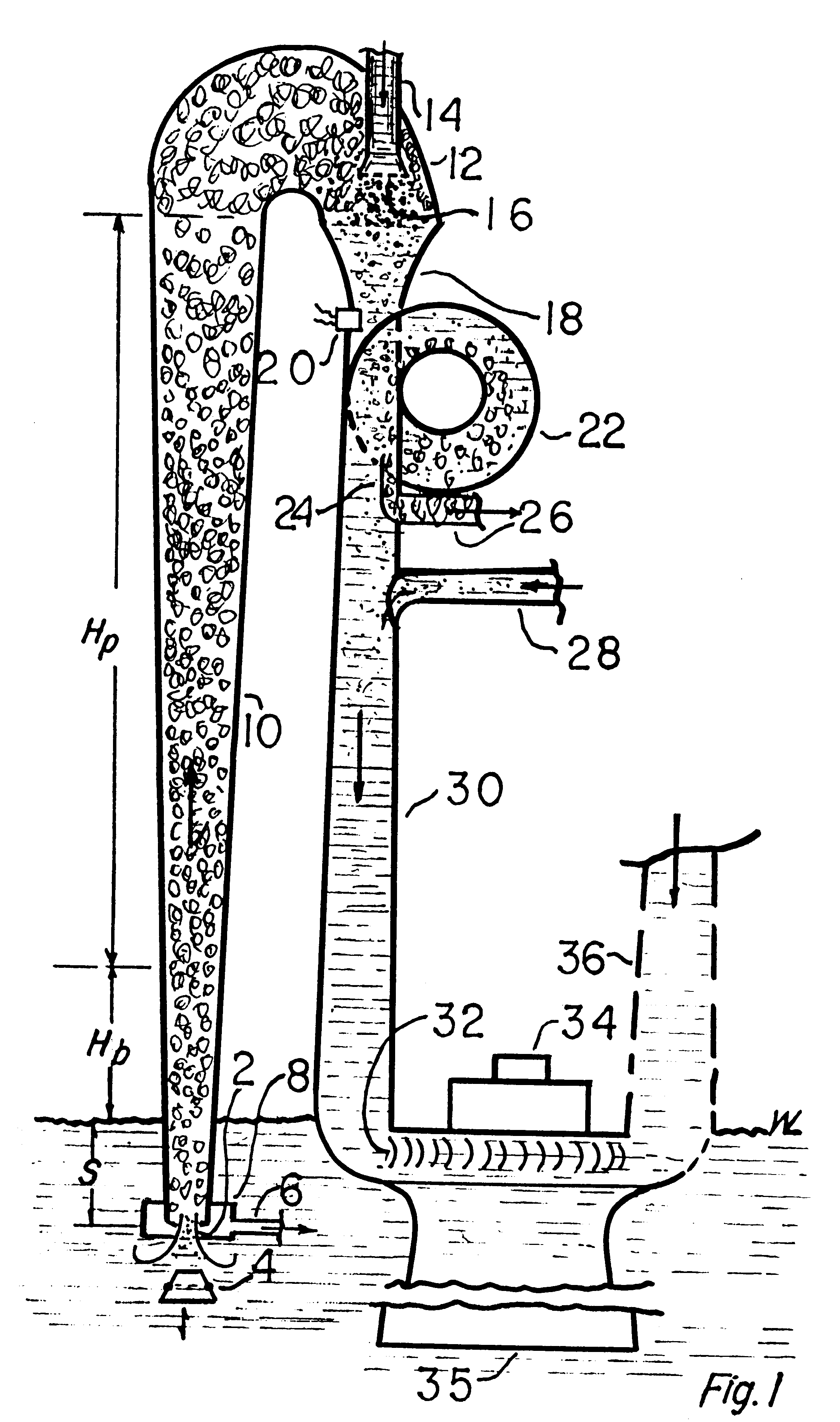
The increase in S increased the length of the SLP, but since the mutlplier (in this treatment asssumed to be 1/0.025) will be 4 and an increased pumping heigt of 4-.DELTA.S. If, for instance we increase S by 1 m, then the theoretical increase in the useful pumping height for producing power, H.sub.p will be 3 m. This approach clearly has its limitations in floating power plants, where the maximum height may be limited by sea keeping considerations such as stability and damage in storms. Nevertheless, some advantage in power production may accrue if very high velocities are developed but not entirely used in the SLP. Increased velocity at the water turbine may be just as useful as increased pressure from a higher head of sea water.
A second and even, at this point less tractable may be discussed inconsideration with the temperature of t

Problems solved by technology

His method was simple but the equipment extremely large and costly.
He was overwhelmed with the sea-going problems because the state of the art in what has become to be known as "Ocean Engineering" was virtually nil.
His equipment came to disasters at the hand of the oceans.
The basic technical fault as I have analyzed his work lay in the fact that he produced very low pressure, high volume steam by throttling.
Claude is known to have produced only a few papers, none specific in the thermodynamics and may never have realized the enormity of these thermodynamically limiting problems.
While this multi-pronged effort (it included work on many problems, from sea-keeping of floating systems, anchoring at sea, to transmission of power in bottom-laid cables to name a few) it did not produce a cost-effective design, All of this work is, of course, available to future system developers.
But titanium, unlike copper-bearing alloys usually used in marine condensers, provides no protection against marine fouling.
As an aside, the marine bronzes of use in condensing achieve a measure of anti-fouling only by wasting of toxic copper ions, so their life is short.
Also, copper is not compatible chemically with ammonia, the probable working fluid (refrigerant) of choice.
Not an optimistic finding at best.
If you then (at considerable cost in power) introduce air bubbles at the lower end, and if they do not all coalesce (as they want to do, unfortunately) then you produce a low-density "foam".
But this device, which promised to be of such value at the time of conception of the OTGHPP, proved to be unworkable as originally concieved.
Unfortunately, my experiments in the late 1970's showed that both the THAC and barometric condenser which were part of the original concept would probably be impractical in this application.
Further experiments on model ALP's and THAC's convinced me that the system would be impractical if (a) the steam bubbles were a

Method used


Image

  • Ocean thermal gradient hydraulic power plant
  • Ocean thermal gradient hydraulic power plant
  • Ocean thermal gradient hydraulic power plant

Examples


Embodiment Construction

The function of the various parts of the OTGHPP except for certain parts of the air bubble separation and vacuum system, which are covered in detail in my new DEGASSER patent, may be understood by following the incoming warm seawater through the system, starting at the intake nozzle 2, FIG. 1. This nozzle serves two functions. First, it controls the amount of water let into the SLP above and second, it releases dissolved air to small bubbles to be used as nuclei for the production of steam bubbles immediately above. Most of the air released into micro bubbles in 2 are not needed for nucleation of steam bubbles, so are isolated during transit through the system until they are re later re-dissolved the higher pressures in the downcomer 30.

The abrupt expansion in cross-section at the nozzle's discharge, 40, in the housing 8 allows for proper velocity and pressure at the point of rapid production of steam bubbles, thus reducing the density of the air-water (foam) mixture in the SLP 10, ...


PUM

PropertyMeasurementUnit
Temperatureaaaaaaaaaa
Lengthaaaaaaaaaa
Pressureaaaaaaaaaa

Abstract

The present patent incorporates major improvements and simplifications of 1976 U.S. Pat. No. 3,967,449 necessary to make the concept functional and useful on a large scale. The earlier patent listed many approaches to the several design problems believed to be necessary at the time of the earlier application, while this one reflects the extensive research and laboratory investigation to identify, validate and demonstrate the functionality of the various parts. In particular, the methods for producing the necessary nuclei for steam bubble production, the method of insuring bubble growth, the method of condensing the steam bubbles produced and methods for minimizing the release of air in large bubbles, and for dealing with those that are released are covered in detail. The first patent, with 50 claims listed many approaches to many problems, some of which were either misunderstood from an unsatisfactory literature or unnecessarily complicated. To an extent those have been eliminated, resulting in what appears to be the simplest embodiment of the concept.

Description

1. Field of the InventionThe present invention relates to improved methods for the design of the various parts of a concept for building power-producing plants using the temperature difference between the warm surface waters of the tropical oceans, typically of the order of 27.degree. C. and the deep bottom waters which may approach the freezing point of salt water but generally are of a higher but useful temperature for condensing the steam bubbles produced. The general method of construction is to introduce the warm surface waters from a preferred depth below the surface, producing steam bubble nuclei, then forming steam bubbles of a desired size. These reduce the density of a rising column of seawater as in the old art of the air lift pump. The ALP, while functional, was poorly understood when this effort was undertaken. In the OTGHPP, The low--pressure steam filling the bubbles is condensed with the cold water pumped from lower ocean depths, the air released is eliminated and th...

Claims


Application Information

Patent Timeline
IPC IPC(8): F03G7/05F03G7/00
CPCF03G7/05Y02E10/34Y02E10/30
Inventor BECK, EARL J.
Owner BECK EARL J
Why Eureka
Try Eureka