Method and apparatus for light modulation and exposure at high exposure levels with high resolution

a light modulation and exposure technology, applied in the field of high resolution methods and apparatus, can solve the problems of difficult design of scanners with extended light sources such as arc lamps, high-power laser diodes or laser diodes, and the inability to collect all the light transmitted by sources into one or more small spots, and achieve the effect of reducing the cost of design

Inactive Publication Date: 2001-03-20
BARCO GRAPHICS
View PDF19 Cites 83 Cited by
  • Summary
  • Abstract
  • Description
  • Claims
  • Application Information

AI Technical Summary

Problems solved by technology

Constructing a scanner with an extended light source such as an arc lamp or a high power laser diode or a laser diode array poses a difficult task for a designer.
Because of the extended size of the source, it is impossible to collect all the light transmitted by the source into one or more small spots, for example of diameter on the order of 10 micrometers at a sufficiently high exposure level.
For low sensitivity media printers such as a laser thermal printer, a higher power laser needs to be used to achieve a high throughput. CO.sub.2 and Nd-Yag lasers do provide high, clean power with nearly Gaussi...

Method used


Image

  • Method and apparatus for light modulation and exposure at high exposure levels with high resolution
  • Method and apparatus for light modulation and exposure at high exposure levels with high resolution
  • Method and apparatus for light modulation and exposure at high exposure levels with high resolution

Examples


Embodiment Construction

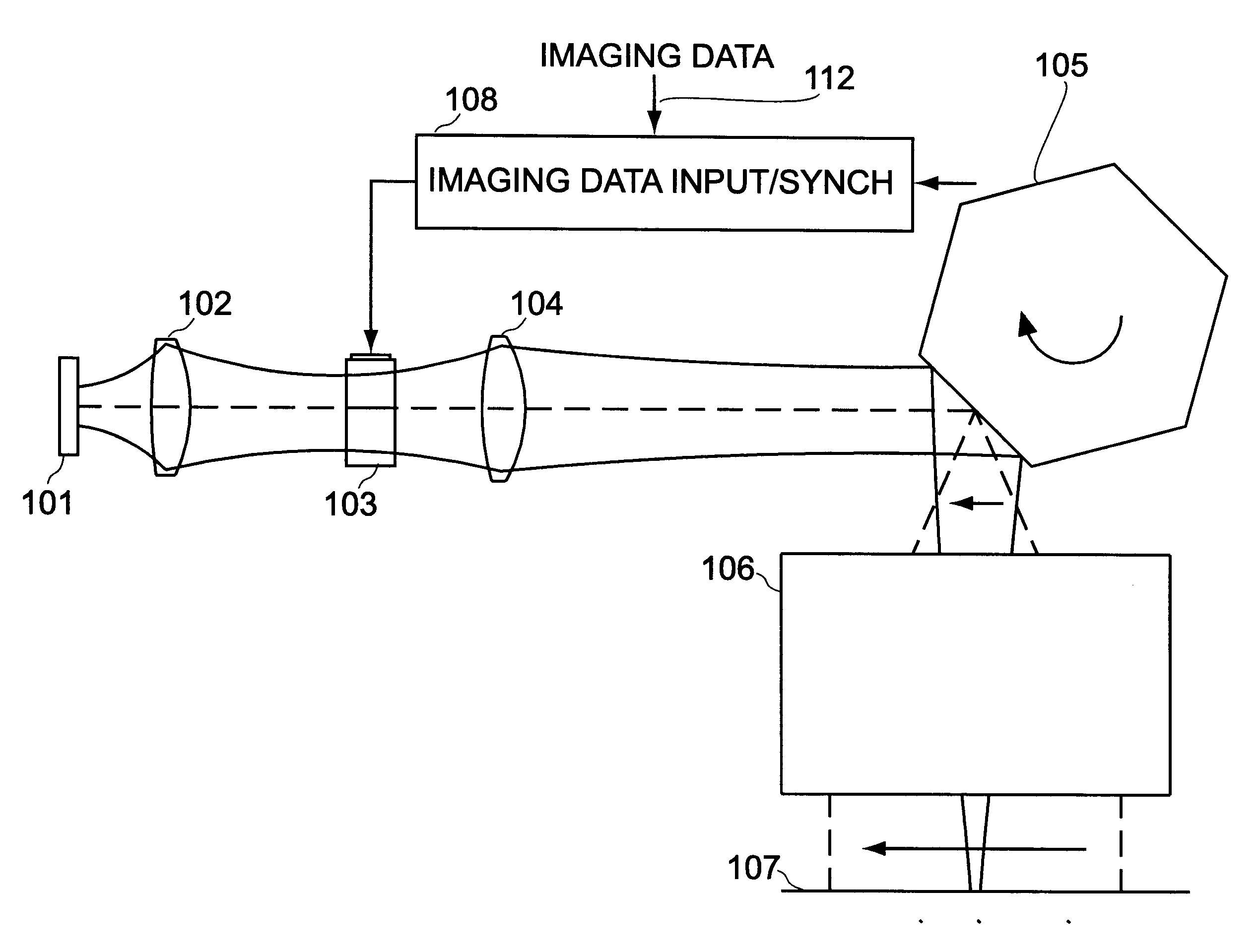
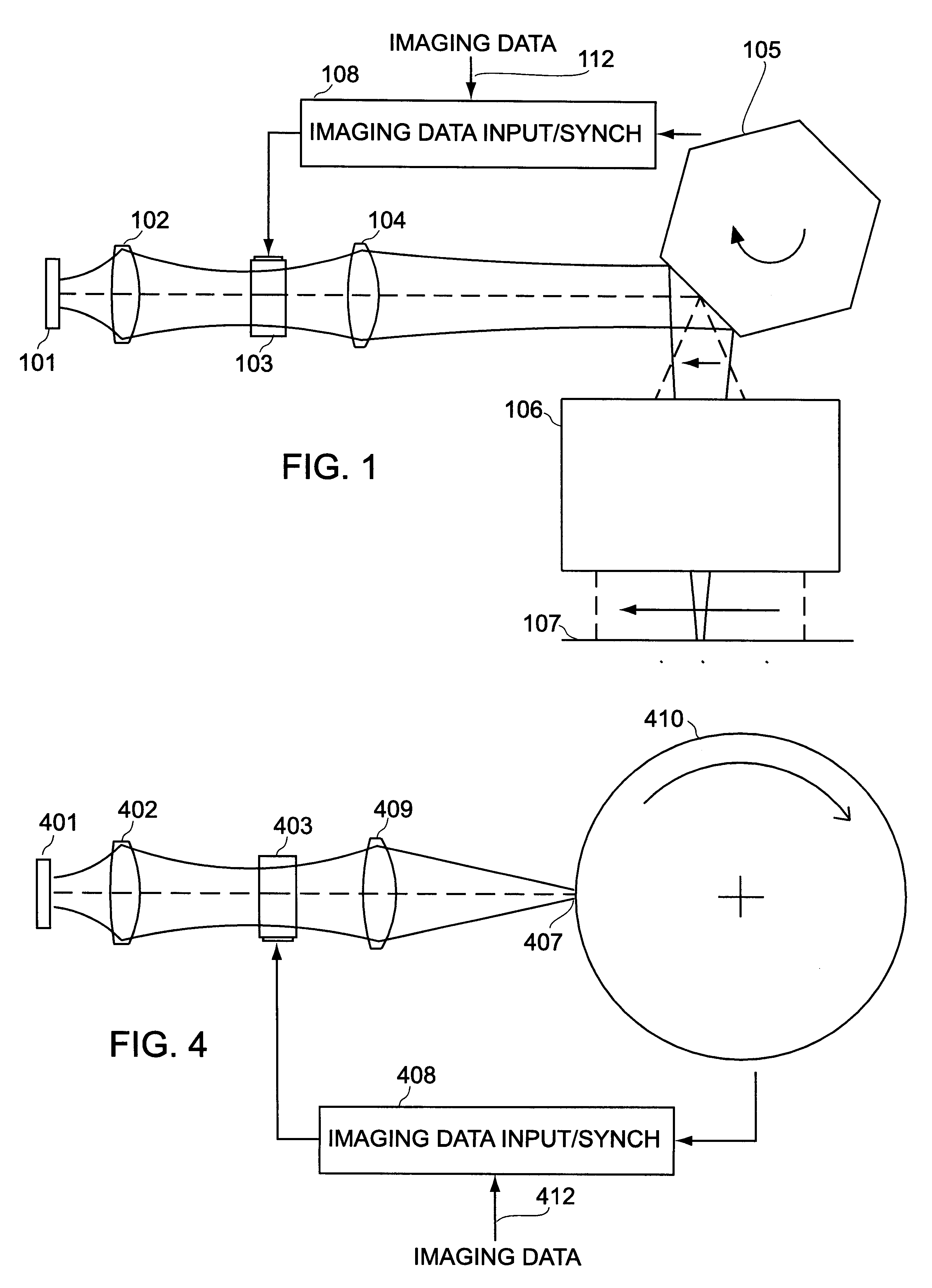
Referring to FIG. 1, in one embodiment, the exposure system consists of a light source 101, a modulator subsystem 103, a scanning means 105 and a light sensitive material held on a focal plane 107.

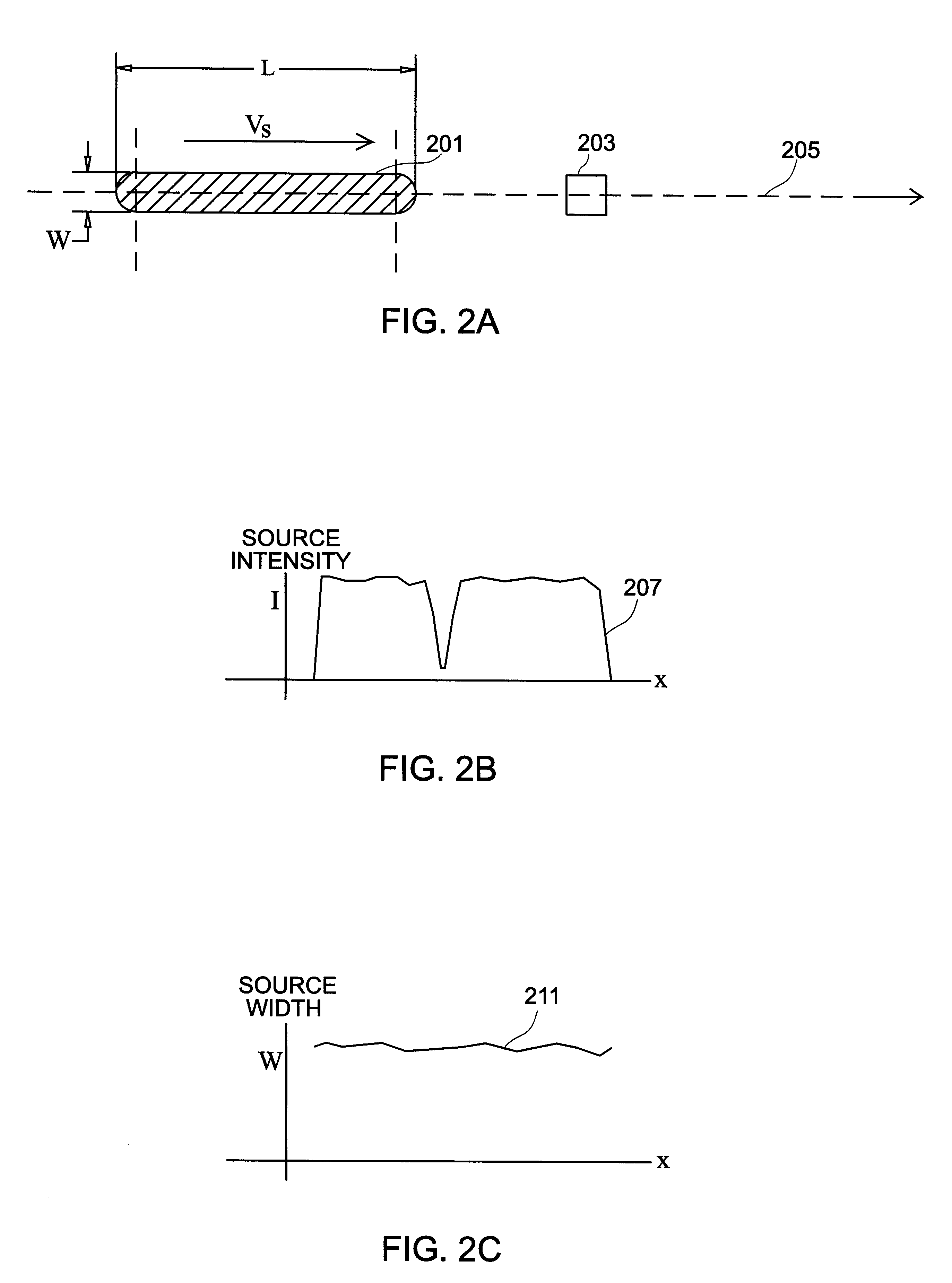
Light source 101 in the preferred embodiment has an approximate line shape and could be, for example, a broad area laser diode which is a line shaped source that produces high beam quality in the direction perpendicular to the junction. In this direction, the source can be imaged onto a very narrow spot (in the order of 5 to 60 microns). In the direction parallel to the junction, on the other hand, it is not possible to focus all the available power onto a small spot. A broad area laser diode with a source dimension of 1 micron by 500 microns and full-width-half-maximum (FWHM) far-field angles of 36 degrees by 10 degrees can be easily imaged by a 4 times magnification system onto a 10 micron by 2000 micron line. Such a source is used in the preferred embodiment. In an alternate implementat...


PUM


Abstract

A method and system for exposing a light sensitive material using device for forming a row of spots of light onto the light sensitive material located on a focal plane, device for modulating each of the spots according to imaging data so that at any point of time, the row of spots forms a data pattern according to the imaging data, device for generating relative motion between the imaging mechanism and the light sensitive material on the focal plane, the direction of motion substantially parallel to the direction of the row of spots on the light sensitive material; and data synchronizing device for shifting the imaging data into the modulating device at a rate determined by the speed of relative motion to maintain the image of any data pattern substantially stationary on the light sensitive material.

Description

This invention is related to optical output scanning and in particular to controlling exposure using extended light sources to achieve high resolution output at a high exposure level.BACKGROUND TO THE INVENTIONConstructing a scanner with an extended light source such as an arc lamp or a high power laser diode or a laser diode array poses a difficult task for a designer. Because of the extended size of the source, it is impossible to collect all the light transmitted by the source into one or more small spots, for example of diameter on the order of 10 micrometers at a sufficiently high exposure level. Laser image recorders typically use lasers with a very well defined optical beam, for example, a low power laser diode, or a gas laser. Such laser diodes provide a high enough beam quality to be focused with high efficiency to a relatively small spot, and thus have been widely used in office laser printers and in the graphic arts industry.For low sensitivity media printers such as a la...

Claims


Application Information

Patent Timeline
IPC IPC(8): B41J2/435B41J2/45B41J2/47G02B26/12
CPCB41J2/451B41J2/471G02B26/12B33Y30/00
Inventor DE LOOR, RONNY A.ROSENFELD, DOV
Owner BARCO GRAPHICS
Why Eureka
Try Eureka