

Protective coating materials for electrochromic devices
- Summary
- Abstract
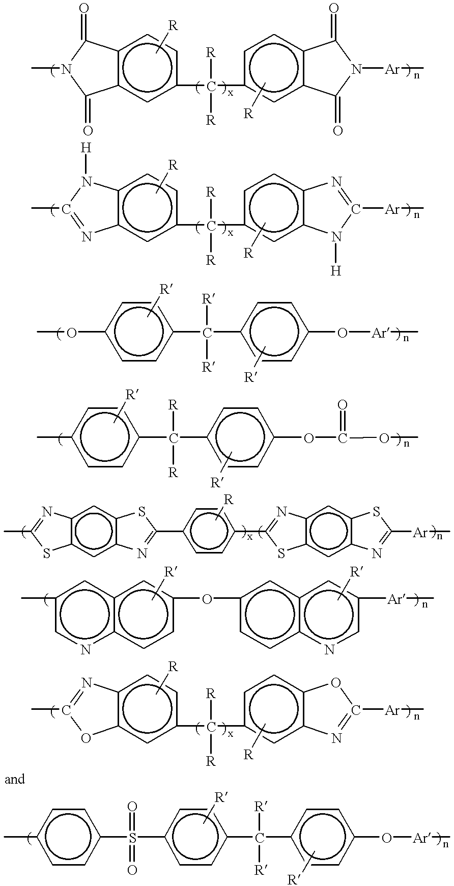
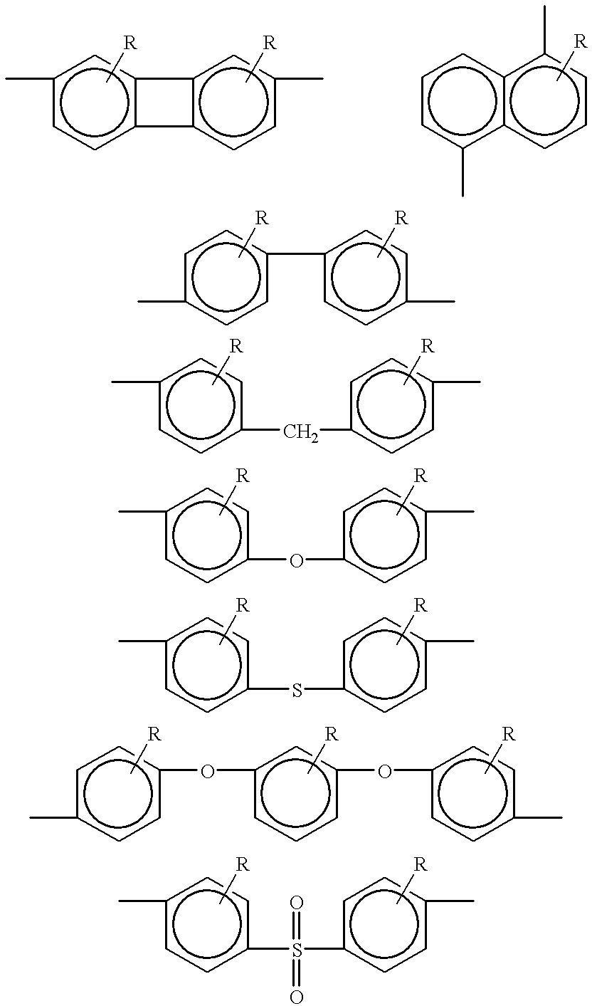
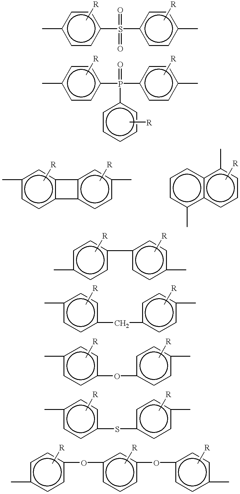
- Description
- Claims
- Application Information
AI Technical Summary
Benefits of technology
Problems solved by technology
Method used
Image

Examples
example 2
FIGS. 4a and 4b illustrate the optical deterioration of an uncoated transparent electrochromic device (FIG. 4a) operated continuously at 85.degree. C. for about 100 hours, compared with the defect-free appearance of a polymeric coated electrochromic device (FIG. 4b) cycled under the same conditions. FIGS. 4a and 4b clearly illustrate the premature deterioration of electrochromic devices that are not protected by a polymeric coating material. The premature deterioration illustrated in FIG. 4a is caused by exposure to surrounding environmental effects. These environmental effects are avoided by providing an environmental protective coating that inhibits moisture, oxygen, chemicals and other contaminates from contacting the electrochromic cell layers as well as maintaining the proper moisture and chemical balance within the electrochromic cell.
example 3
In a preferred embodiment, a polymeric coated electrochromic device was formed by purifying a necessary quantity of an alpha-[1,4-Biphenylyl]-omega-[4-[[4(4-phenylphenoxy)phenyl]phenylphosphinyl]phenoxy]-poly[oxy-1,4phenylene (phenlphosphinylidene)-1,4-phenyleneoxy-1,4-phenyleneoxy-1,4-phenylene[2,2,2-trifluoro-1-(trifluoromethyl)ethylidene]-1,4-phenylene (hereinafter "6-P polymer") polymer. A 10% by weight polymeric solution of the purified 6P polymer was prepared using an appropriate amount of chlorobenzene. The 10% (by weight) polymeric solution was filtered twice using 5.0 micrometer Teflon membrane and then, for final refinement, a 0.2 micrometer membrane filter to remove any solid particles. The polymeric solution was then out-gassed under a vacuum for 30 minutes to remove any remaining micro-bubbles or dissolved gasses.
An electrochromic cell with bus bars which had been deposited onto a glass substrate was obtained. The bus bars were covered with an adhesive tape so that the ...
PUM
 Abstract
Description
Claims
Application Information