Method and apparatus for measuring NOx gas concentration

a technology of nox gas and concentration, applied in the direction of instruments, specific gravity measurement, material electrochemical variables, etc., can solve the problem of inaccurate measurement of nox concentration, and achieve the effect of reducing temperature dependency and oxygen concentration dependency

Inactive Publication Date: 2001-04-10
NGK SPARK PLUG CO LTD
View PDF40 Cites 37 Cited by
  • Summary
  • Abstract
  • Description
  • Claims
  • Application Information

AI Technical Summary

Benefits of technology

The feature of the NO.sub.x gas concentration sensor according to an embodiment of the present aspect (2--2, 2-3) is explained by referring to FIGS. 41 (A)-(C) illustrating a sensor according to an example of the present invention and to FIG. 49 illustrating a sensor according to a reference example concerning the present aspect. The present invention, however, is not limited to the sensor shown in FIG. 41. The sensor shown in FIG. 41 differs from the sensor shown in FIG. 49 in that, in the sensor of FIG. 41, the distal ends towards the second diffusion aperture 63 of the electrodes 66a, 66b of the first oxygen pumping cell 66 have been removed (A>B). Therefore, the length of each of the electrodes 66a, 66b is shorter and hence the electrode area is smaller in the sensor of FIG. 41. By the electrodes of the first oxygen pumping cell 66 being shorter in length, the oxygen concentration gradient in the first measuring chamber 2 in particular in the measuring gas flow direction (direction pro...

Problems solved by technology

According to the finding reached by the present inventors, the above method has a drawback that, if H....

Method used


Image

  • Method and apparatus for measuring NOx gas concentration
  • Method and apparatus for measuring NOx gas concentration
  • Method and apparatus for measuring NOx gas concentration

Examples


example c1

Referring to the drawings, a C1 example of the present aspect C is explained.

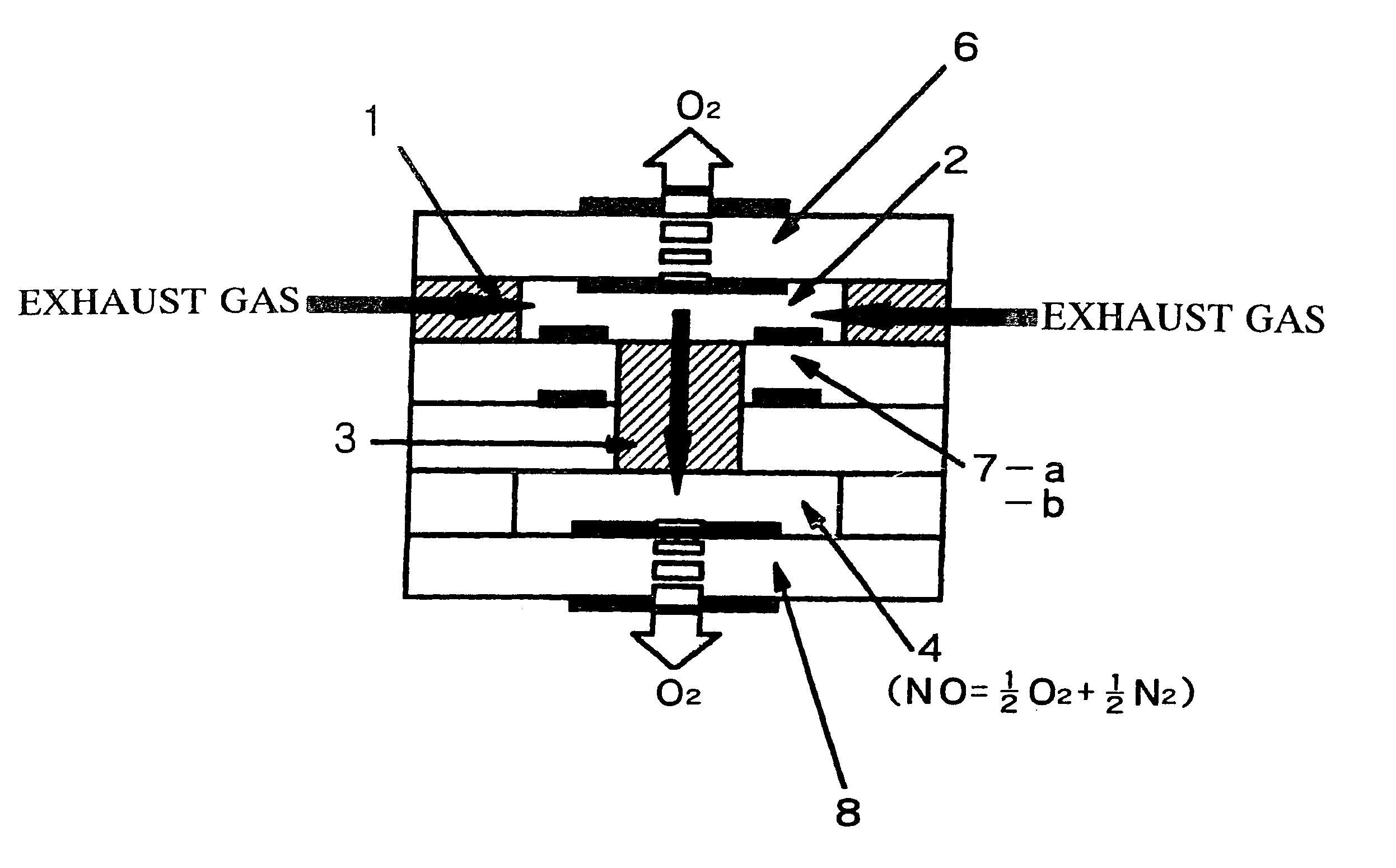
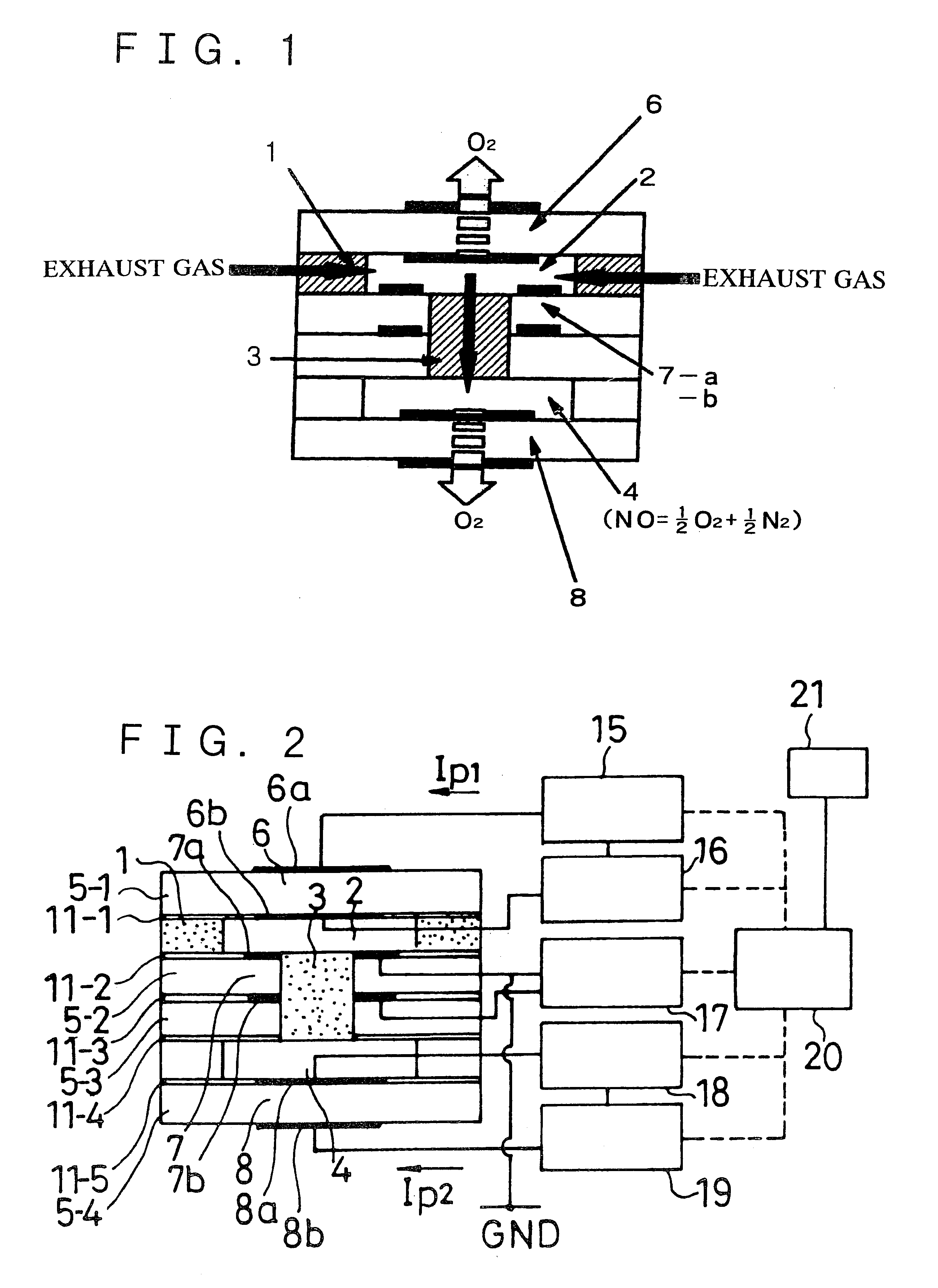
FIGS. 41A to 41C illustrate a NO.sub.x gas concentration sensor according to an embodiment of the present aspect, where FIG. 41A is a cross-sectional view taken along the long-side direction, FIG. 41B is a plan view showing a first measuring chamber and FIG. 41C is an enlarged cross-sectional view showing essential portions of the first measuring chamber. The sensor of FIG. 41 includes a layer of the first oxygen pumping cell 66 having a solid electrolyte layer and an electrode 66a (positive electrode) and a negative electrode 66b on both sides of the solid electrolyte layer, an oxygen concentration measuring cell 67 having another solid electrolyte layer and an oxygen concentration measuring cell 67 having oxygen partial pressure measuring electrodes formed on both sides of the solid electrolyte layer and a second oxygen pumping cell 68 having a third electrolyte layer and oxygen pumping electrodes on both...


PUM


Abstract

This is a method and apparatus for accurately determining a NOx concentration of a measurement gas that contains H2O and/or CO2, without being affected by a dissociation of H2O and/or CO2.In this method and apparatus,(1) the NOx-measurement gas containing H2O and/or CO2 is introduced to travel through a heated flow channel formed by an oxygen ion conductive solid ceramic electrolyte body that electrically control amount of O2 from the flow channel,(2) while said measurement gas travels, a residual gas including NO and H2O and/or CO2 is formed from the measurement gas,(3) said residual gas is flowed to contact a catalytic electrode to which a negative polarity of a low voltage that does not dissociate H2O and/or CO2 but dissociates NO is applied, so that said electrode dissociates a NO gas of the residual gas into N ions and O ions and flows an electric current through the electrolyte body in proportion to an amount of the O ions dissociated from said residual gas at the electrode, and(4) the NOx concentration in the measurement gas is determined based on the current.The low voltage preferably applied in the above (3) is about 350-450 mV.

Description

This invention relates to a method for measuring the concentrations of the NOx gas and an apparatus or sensor for carrying out the measurement method. More particularly, it relates to a method for measuring the NOx gas concentration used in exhaust gases containing a large quantity of H.sub.2 O, and a NOx gas concentration sensor.Recently, researches into directly measuring the concentration of the NOx gas for controlling the infernal combustion engine or catalysts are proceeding in meeting with intensification of regulations on vehicle exhaust gases.In particular, researches are going on extensively for a NOx gas concentration sensor of the type in which the oxygen is pumped out by a first oxygen ion pump cell using a solid electrolyte (oxygen conductor) such as zirconia, so as not to cause decomposition of the NOx gas (2NO.fwdarw.N.sub.2 +O.sub.2) by the first oxygen ion pump cell and in which oxygen is further pumped out from the NOx-gas-containing residual gas by the second oxyg...

Claims


Application Information

Patent Timeline
IPC IPC(8): G01N27/407G01N33/00
CPCG01N27/4074Y10T436/179228
Inventor ANDO, MASASHIISHIDA, NOBORUSUGAYA, SATOSHIOSHIMA, TAKAFUMINADANAMI, NORIHIKOOOTUKA, TAKAKISATO, YOSHIKUNIOKUMURA, TATSUO
Owner NGK SPARK PLUG CO LTD
Why Eureka
Try Eureka