Biodegradable implant manufactured of polymer-based material and a method for manufacturing the same

a biodegradable implant and polymer-based technology, which is applied in the field of biodegradable implants manufactured of polymer-based materials and a method for manufacturing the same, can solve the problems of affecting the health of patients, affecting the quality of life of patients, so as to achieve the effect of reducing the risk of infection

Inactive Publication Date: 2001-05-08
BIONX IMPLANTS
View PDF33 Cites 220 Cited by
  • Summary
  • Abstract
  • Description
  • Claims
  • Application Information

AI Technical Summary

Problems solved by technology

Their biostable parts, e.g. fibres, plastic and metal threads or rings or tubes or the like remain in the system even after an organ or a tissue has healed, and therefore such implants and devices can later be harmful to the patient, causing e.g. infections, inflammatory reactions, foreign body reactions and / or particles or corrosion products or the like can be released therefrom, which can further cause harmful reactions in the system.
However, typically tubular implants and surgical devices involve the drawback that they degrade evenly at their entirely length, that is, the gradient of biodegration is directed to the centre of the cross section along the entire length of the implant or the corresponding surgical device.
Thus, known elongated implants and surgical devices lose their strength evenly at their entire length, and finally the whole implant or surgical device loses its strength in a relatively short period of time at its entire length.
In case the disintegrating implant or surgical device is placed inside a hollow, elongated organ or tissue, it is possible that an uncontrollable quantity of particles and pieces is released from the disintegrating implant or the surgical device in a short period of time, wherein some of these parts and particles can join together and can contribute to a stoppage in the hollow tissue or organ, such as in a flow duct of a blood vessel, urinary tract or other tubular organ or tissue.

Method used


Image

  • Biodegradable implant manufactured of polymer-based material and a method for manufacturing the same
  • Biodegradable implant manufactured of polymer-based material and a method for manufacturing the same
  • Biodegradable implant manufactured of polymer-based material and a method for manufacturing the same

Examples


example 2

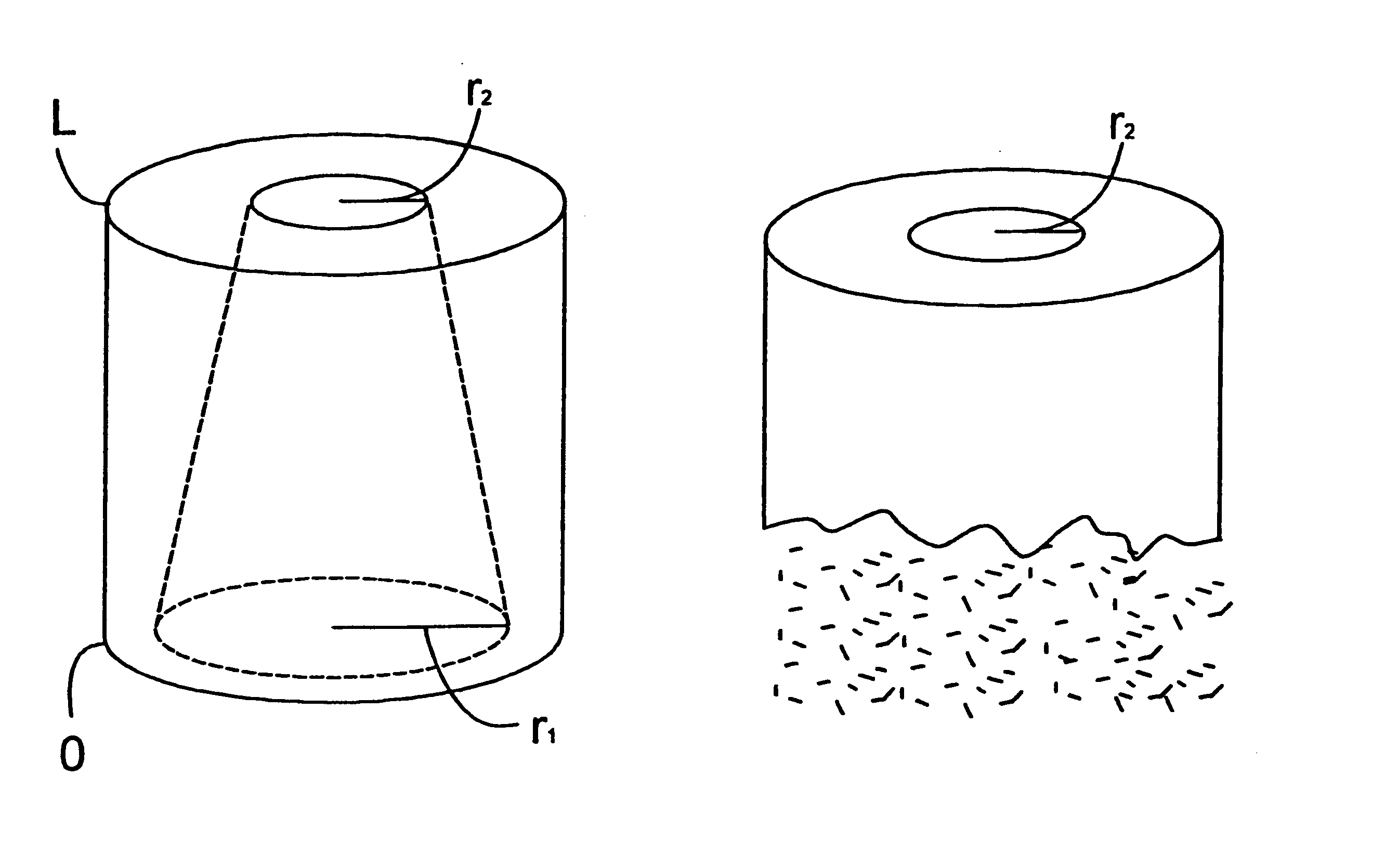
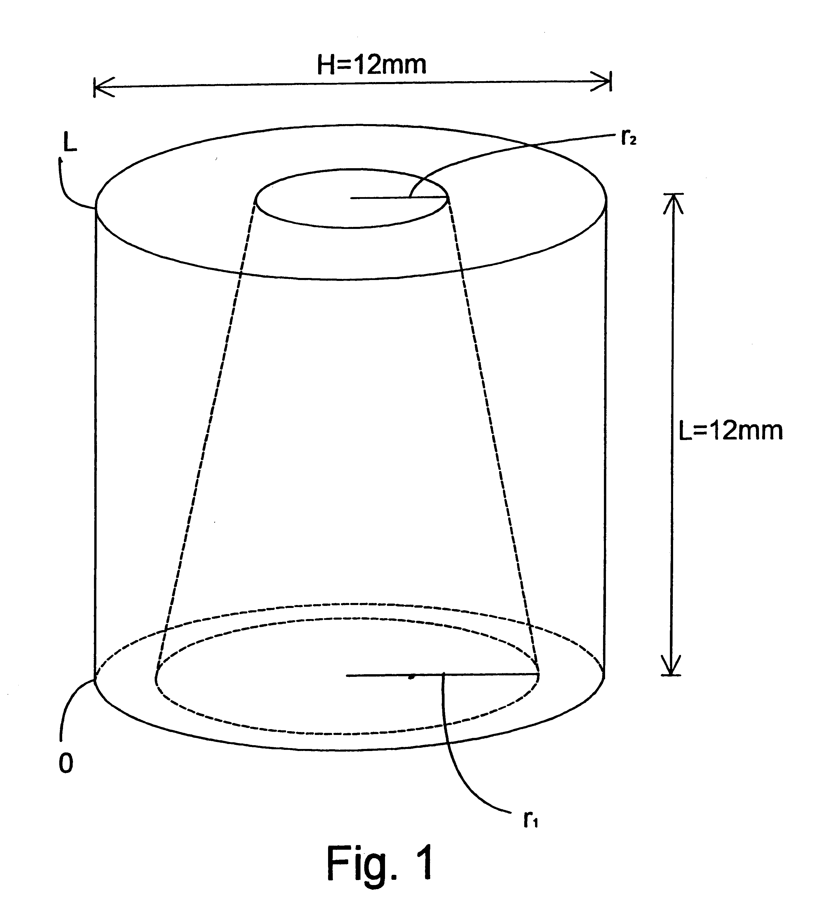
There were manufactured implants having a height of 12 mm, a diameter of 12 mm and a cylindrical central hole 1 in the direction of longitudinal axis of the cylindrical configuration and with a constant diameter of 10.

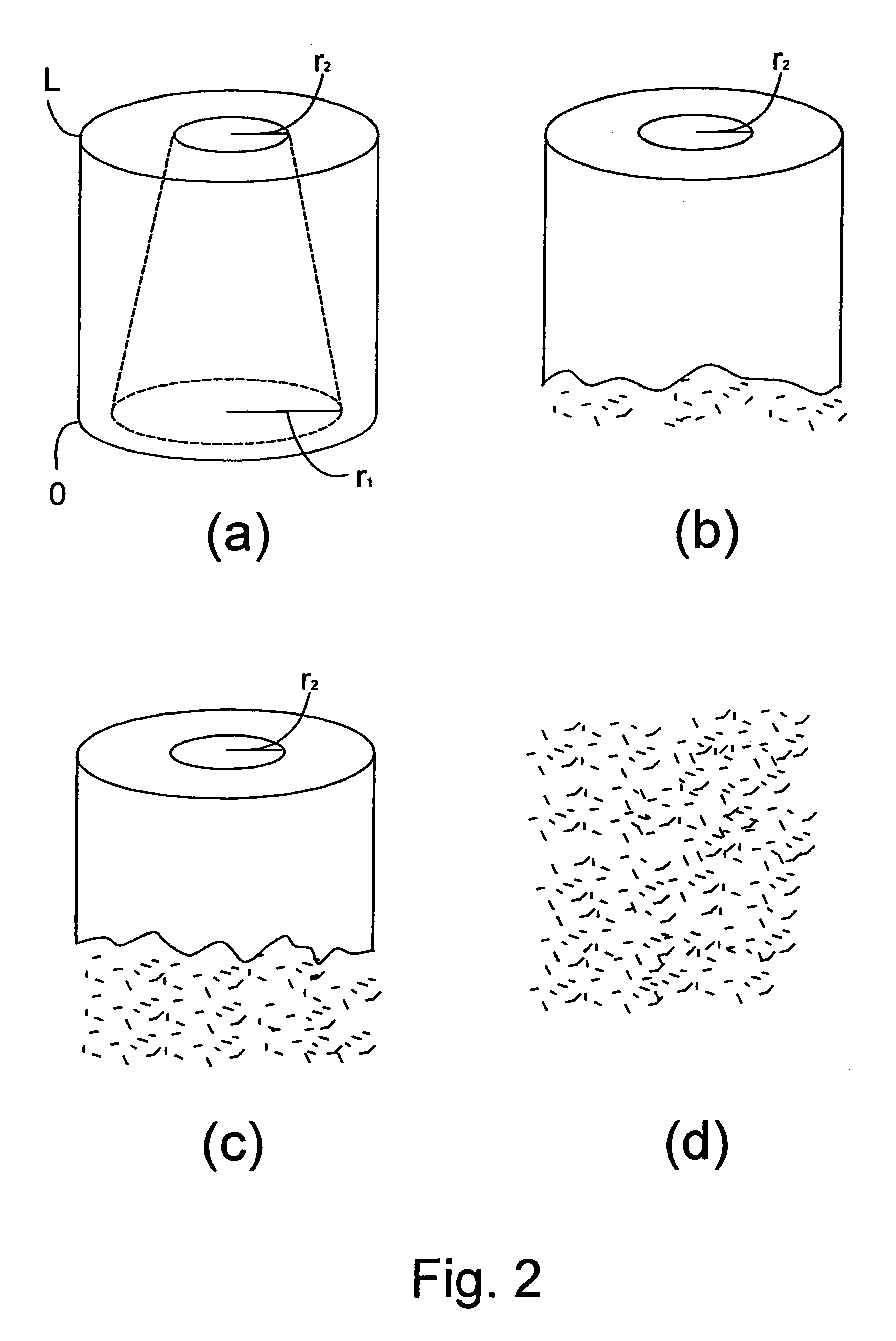
In the curved outer surface of the implants, there were drilled smaller radial-directed holes extending to the central hole 1 in a following manner: at the first end of the implant, close to its edge and in the direction of the periphery, around the implant holes were drilled having a diameter of 2 mm and extending to the central hole, between which holes a strip of 0.5 mm was left in the outer surface of the implant in the direction of periphery. Above this line of holes RR1 (FIG. 2), in a corresponding manner as the line of holes RR1, there were drilled other holes having a diameter of 1.5 mm having strips of 1 mm between them in a manner that between the first RR1 and the second RR2 line of holes, strips of 1 mm were left. Above the second line of holes RR2, in a co...

example 3

Preform having a width of 3 mm was manufactured by extrusion (single-screw extruder) of polyglycol according to Example 1, which preform was cooled to room temperature by means of moving cloth. Bars of 1 m were cut out of the blank. A series of bars 2 were vertically attached parallel at the same horizontal level at the second end to a chuck jaw structure 3 of a pre-hydrolysis apparatus according to FIG. 4. The chuck jaw structure 3 had been coupled to a vertical conveyor 5 in connection with a body 4, by means of which vertical conveyor it was possible to lift and lower a series of bars 2T slowly in the vertical direction. The lower ends of the series of bars 2T were thus free ("free end"). By means of the vertical conveyor 5 the bars 2 were pre-hydrolyzed in a buffer solution of Example 1 at a temperature of 37.degree. C. by lowering them slowly in a buffer solution 7 in a tank 6, placed below the bar series 2T, by means of the vertical conveyor 5 of the chuck jaw structure 3, and...

example 4

Cylindrical preform having a diameter of 3 mm was manufactured of amorphous (non-crystalline) lactide copolymer (Resomer, LID molecular ratio 85 / 15, M.sub.v =200,000, manufactured Boehringen / lngelheim, Germany) by extrusion (single-screw extruder), which preform was cooled to a room temperature on a moving cloth. A pre-hydrolysis apparatus according to FIG. 5 was created for the test arrangement. Out of the above mentioned preform, bars 2 having a length of 1 m were cut and placed as a series of bars 2T to a vertical, isolated tank 10 at a mounting bracket 11 belonging to the apparatus in a manner that the bars 2 were apart from each other in the vertical direction. By using a pump 12 in the lower part of the tank, phosphate buffer solution 15 according to Example 1 was pumped at a temperature of 70.degree. C. slowly to the tank in a manner that the filling of the tank 10 took 10 hours. As soon as the fluid surface had risen to the level of the upper ends of the bars in the series o...


PUM

PropertyMeasurementUnit
thicknessaaaaaaaaaa
thicknessaaaaaaaaaa
temperatureaaaaaaaaaa

Abstract

The invention relates to a biodegradable implant or the like manufactured of polymer-based material and intended to be installed in tissue conditions. In the macroscopic structure of the implant two or several zones are created in a manner that the biodegradable polymer-based material has in different zones a different detaching time from the macroscopic structure under tissue conditions.

Description

The invention relates to a biodegradable implant or the like manufactured of polymer-based material and intended to be installed in tissue conditions.BACKGROUND INFORMATIONIn surgery, it is known to employ biodegradable, elongated, typically tubular surgical implants and devices for supporting or combining or dividing elongated organs, tissues or parts thereof. These objects include various canals, ducts, intestines, blood vessels, tubes, such as bronchial tubes, urinary tracts, nerves etc.In this context, the biodegradable material refers to a material manufactured of polymer, copolymer or polymer composition, the degradation and / or absorbing of which material takes place by means of metabolic reactions and / or secretion through kidneys, lungs or intestines or skin.A multitude of publications describe various tubular implants and surgical devices manufactured of biostable or biodegradable materials. Such implants are disclosed e.g. in publications U.S. Pat. Nos. 3,108,357; 3,155,095...

Claims


Application Information

Patent Timeline
Patent Type & Authority Patents(United States)
IPC IPC(8): A61L27/58A61L27/00A61L27/50A61L31/14A61F2/02
CPCA61F2/04A61F2/82A61L27/50A61L27/58A61L31/14A61L31/148A61F2210/0004A61F2250/003
Inventor TORMALA, PERTTIVALIMAA, TERO
Owner BIONX IMPLANTS
Why Eureka
Try Eureka