Method for blasting an inside surface of a cylinder

a technology of inside surface and cylinder, which is applied in the direction of grinding/polishing apparatus, grinding machines, manufacturing tools, etc., can solve the problems of undesirable distribution change, uneven distribution of particle size, and the above-mentioned methods each have problems, etc., to achieve uniform rough surface, uniform rough surface, good rough surface

Inactive Publication Date: 2001-06-12
SUZUKI MOTOR CORP
View PDF8 Cites 28 Cited by
  • Summary
  • Abstract
  • Description
  • Claims
  • Application Information

AI Technical Summary

Benefits of technology

According to the present invention, blast particles are blown in the slant downward direction from a blast gun, by which an inside surface of a cylinder extending in the vertical direction of a workpiece is blasted downward. Therefore, the blast particles do not accumulate in the cylinder, and a uniformly rough surface can be obtained. Also, the inside surface is not affected by rebounding particles, so that a good rough surface can be obtained.
Also, According to the present invention, a cylinder block is placed upright with a cylinder head mating surface on the upper side, a masking member is mounted on the cylinder head mating surface, and blast particles are blown in the slant downward direction from a blast gun, by which an inside surface of a cylinder is blasted downward. Therefore, the blast particles do not accumulate in the cylinder, and a uniformly rough surface can be obtained. Also, the inside surface is not affected by rebounding particles, so that a good rough surface can be obtained. Further, the cylinder head surface and the inside surfaces of other cylinders can be protected, a masking member mounting / dismounting process for each workpiece can be omitted, and the storage space for the masking member can be reduced.

Problems solved by technology

However, the above-mentioned methods each have problems as described below.
In Japanese Patent Provisional Publication No. 60-44267, although a specified particle size distribution can be obtained in the initial state, the abrasive particles, once being blown, are broken, so that the distribution changes undesirably.
Therefore, it is difficult to specify the particle size distribution in high volume production.
Also, in Japanese Patent Provisional Publication No. 64-58477, the blast nozzle has to come into contact with the base material to take advantage of the vacuum blaster type, so that there is the possibility of the surface of base material being damaged.
The blast nozzle must be changed for each cylinder to blast cylinders of various diameters, so that the facility is complicated.
Since the blast nozzle is in contact with the base material, the once-roughened surface is rubbed by the blast nozzle, so that the roughening state is deteriorated.
Thus, although the blasting process contributes greatly to the quality of the thermal spray deposit, a satisfactory method of obtaining the rough surface in the cylinder has not been disclosed in any Publications.
Once the blast particles get into the screw holes or the like, they cannot be removed easily by cleaning etc.
If the blast particles remaining in the screw holes or the like are left unremoved, they bite into the inside surface of cylinder when the engine is assembled, leading to poor assembly.
(5) Since blasting is performed to roughen the surface, the masking plates are consumed heavily.
Therefore, the mechanism is complicated, and also the number of moving parts increases.
As a result, a trouble caused by biting of blast particles occurs easily.
Also, the movement mechanism of blast gun is subjected to restrictions as to the movement of blast gun and the size of mechanism by the size of the cabinet.
Further, the apparatus must have a sufficient dust collecting function corresponding to the capacity of cabinet, so that the space for the cabinet itself is increased, and the apparatus becomes larger.

Method used


Image

  • Method for blasting an inside surface of a cylinder
  • Method for blasting an inside surface of a cylinder
  • Method for blasting an inside surface of a cylinder

Examples


first embodiment

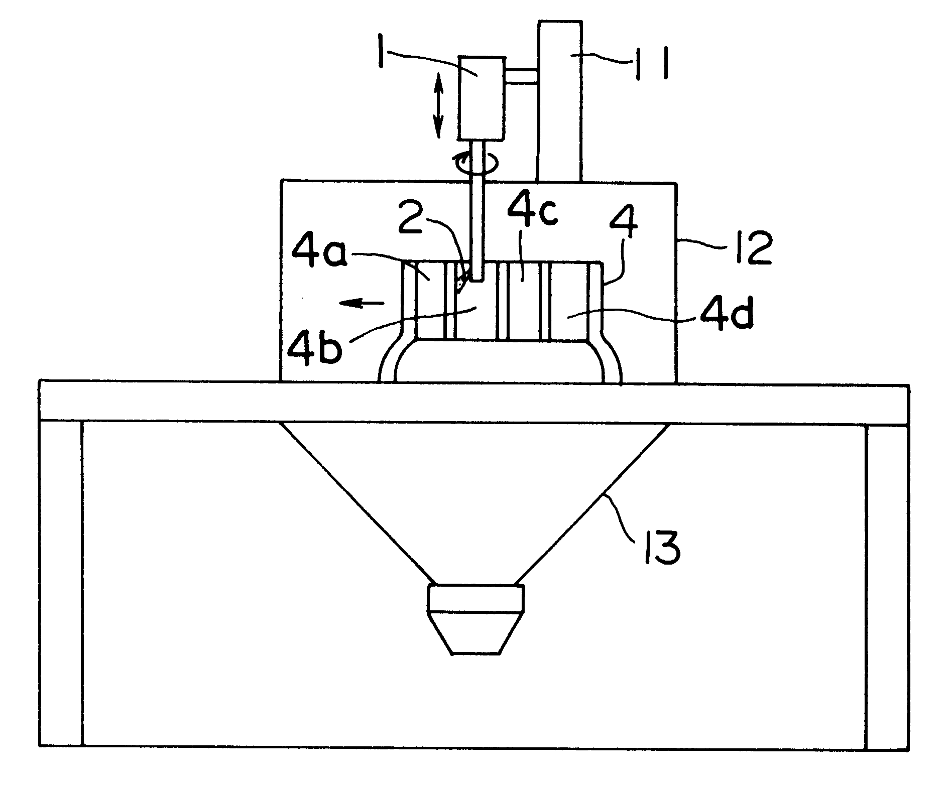
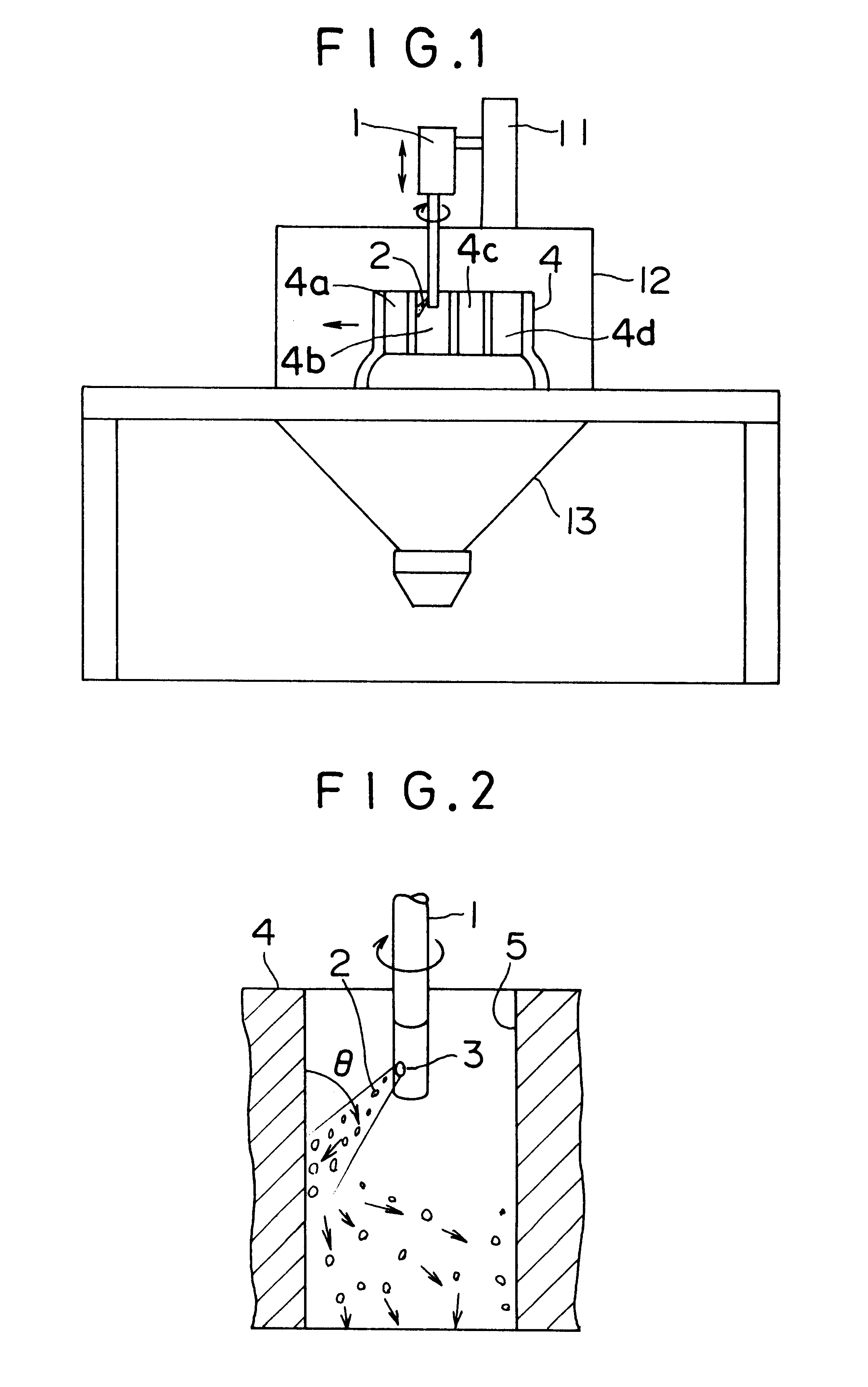
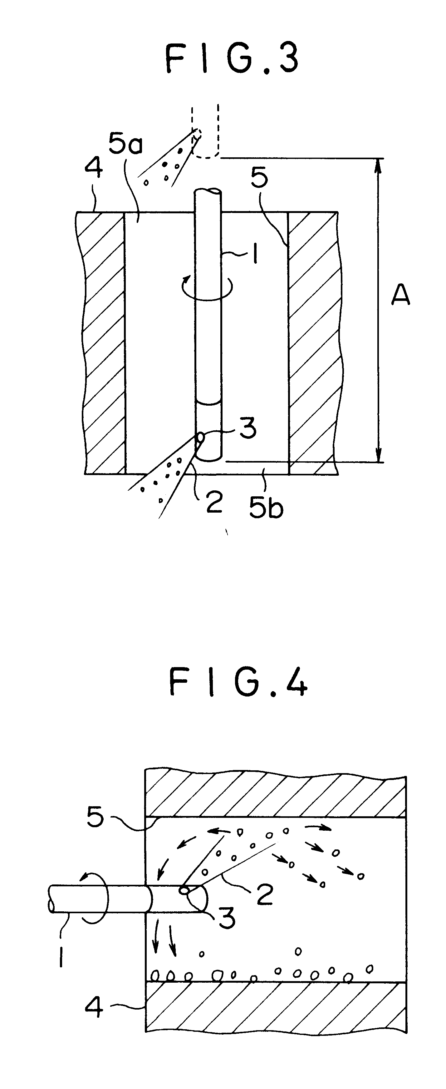
FIGS. 1 to 9 are drawings for illustrating the present invention, FIG. 1 is a schematic view showing a case where a cylinder of an internal combustion engine is blasted as an example of an inside surface of a cylinder; FIG. 2 is a partially enlarged view showing a state in which an inside surface of the cylinder is blasted; FIG. 3 is a partially enlarged view showing a movement of a blast gun in the case of FIG. 2; FIG. 4 is a partially enlarged view showing a case where a cylinder block is placed horizontally; FIG. 5 is a partially enlarged view schematically showing the movement paths of blast particles in blasting; FIGS. 6 and 7 are partially enlarged views showing a relationship between the direction in which the blast gun is moved and the direction in which the blast particles are blown; FIG. 8 is a partially enlarged view showing a relationship between the cylinder being blasted and a masking member; FIG. 9 is a partially enlarged view in which the masking member shown in FIG....

second embodiment

Next, the present invention will be described with reference to FIGS. 10 to 13. FIG. 10 is a schematic front view of the whole blasting apparatus; FIG. 11 is a schematic right side view of FIG. 10; FIG. 12 is a partially enlarged view showing a modification of a masking member; and FIG. 13 is a schematic sectional view schematically showing the flow of air.

A rotating blast gun 1 is fixed to a uniaxial traverser 11, and the vertical movement thereof is controlled to the Z direction. As shown in FIGS. 10 and 11, a transfer path 7 using rollers 7a is provided under the blast gun 1. A pallet 8 can be conveyed on this transfer path 7 while being controlled. Therefore, a cylinder block 4 placed on the pallet 8 is moved and automatically positioned so that the center axis of each of cylinders 4a to 4d coincides with the center axis of the rotating blast gun 1.

On the pallet 8, rims 8a are erected so as to coincide with the shape of crank journal. By placing the cylinder block 4, the cylinde...


PUM

PropertyMeasurementUnit
diameteraaaaaaaaaa
diameteraaaaaaaaaa
heightaaaaaaaaaa

Abstract

The present invention provides a method for blasting an inside surface of a cylinder, in which a steady rough surface is always obtained efficiently in the whole region of inside surface of cylinder for an internal combustion engine. For this purpose, a blast gun 1, which is provided so as to be moved vertically by a traverser 11 and capable of rotating around the axis thereof, has a blast nozzle 3 for blowing blast particles 2 in the vicinity of the lower end thereof. The blowing direction of the blast nozzle 3 is slant downward. A cylinder block 4 is placed upright so that the axis of each cylinder is vertical with a cylinder head mating surface 4e on the upper side, and is isolated from the surrounding space by a cabinet 12. The blast gun 1 blows the blast particles 2 while lowering in each cylinder of the cylinder block 4, by which the inside surface 5 of cylinder is blasted. A blast particle recovering reservoir 13 is provided under the apparatus to recover the blast particles 2.

Description

FIELD OF THE INVENTION AND RELATED ART STATEMENTThe present invention relates to a method for blasting an inside surface of a cylinder, in which an inside surface of a cylinder of a workpiece, for example, an internal combustion engine cylinder is blasted.The methods for blasting an inside surface of an internal combustion engine cylinder includes a method in which the surface of a base material is roughened by blasting as a preceding process of thermal spraying and a method in which a blast deposit is formed (for example, a method disclosed in Japanese Patent Provisional Publication No. 8-333671 (No. 333671 / 1996)).In the blasting method as a preceding process of thermal spraying, abrasive particles such as alundum, densic, and steel are blown against the surface of a base material by using compressed air or motor power to roughen the surface of the base material. For example, in the method disclosed in Japanese Patent Provisional Publication No. 60-44267 (No. 44267 / 1985), coarse bl...

Claims


Application Information

Patent Timeline
Patent Type & Authority Patents(United States)
IPC IPC(8): B24C3/32B24C3/00B24C1/06B24C3/16B24C9/00
CPCB24C3/325B24C3/083
Inventor MIYAI, KENJIKUNIOKA, SEIYATAKAHASHI, TADASHI
Owner SUZUKI MOTOR CORP
Why Eureka
Try Eureka