Lightning locating system

Inactive Publication Date: 2001-06-12
STRATEGIC DESIGN FEDERATION W LLC
View PDF19 Cites 98 Cited by
  • Summary
  • Abstract
  • Description
  • Claims
  • Application Information

AI Technical Summary

Benefits of technology

In another embodiment, a lightning detection system includes a single sensor for determining the location of an into a lightning discharge (RF pulse) The initial pulses are monopolar, either positive or negative and about one microsecond or less in duration. The sensor includes an E-field antenna and a crossed loop antenna. A distance for the initial discharge is determined from the amplitude of the detected pulse which is constant for initial pulses. Since the initial discharge is vertic

Problems solved by technology

Thus, such a system typically will not detect IC lightning.
A further disadvantage of prior single sensor systems is susceptibility to RF noise.
Since Very Low Frequency (VLF) signals are targeted for detection, systems for detecting CG return strokes can provide a general bearing of a storm using well known crossed loop technology, but are subject to gross errors with response to distance.
Thus it will be appreciated that these VLF systems do not have the capability to accurately determine lightning range from a single observation station.
Another disadvantage of known systems stems from display limitations with respect to lightning position More particularly, a single dot on a display typically represents a complete lightning flash.
Thus a display of dots may provide a general area containing lightning discharges, but does not provide an accurate representation of the location of the source of the atmospheric disturbance.
A still further drawback of some systems is that in operation, the systems detect and process energy from many parts of the lightning channels of lightning strokes and the multitude of pulses from each stroke, thus requiring a tremendous processing capability.
Such systems are complex and expensive.
With respect to known VLF single station lightning detection systems, there are considerable limitations associated therewith due to the inherent variation in lightning stroke discharge amplitudes.
This produces polarization errors for azimuth and distance determination.
These factors contribute to the problems of fabricating an accurate lightning detection system including the ability to distinguish between IC and CG lightning.
Microbursts pose a thr

Method used


Image

  • Lightning locating system
  • Lightning locating system
  • Lightning locating system

Examples


first embodiment

a lightning detection system 100 includes five sensors 102 and a master station 104 for collecting and processing data from the sensors. The sensors 102 are configured in spaced apart relationship wherein the exact location of each sensor is known to the master station 104. In an exemplary embodiment, sensors 102 are placed in a cross-configuration with one sensor centrally located within the cross and disposed within a twenty-five mile radius. A (Global Positioning System) GPS unit associated with each sensor can provide a location accurate to about fifty feet, but in an illustrative implementation, the accuracy of each sensor with respect to latitude and longitude is known to within 10 feet. Each of the sensors 102 is connected to the master station 104 via telephone line or by a RS-232 serial computer link 106. An RS-232 link is adapted for a sensor in the vicinity of the master station.

Different configurations of the sensors are possible in alternative embodiments. For a three-d...

second embodiment

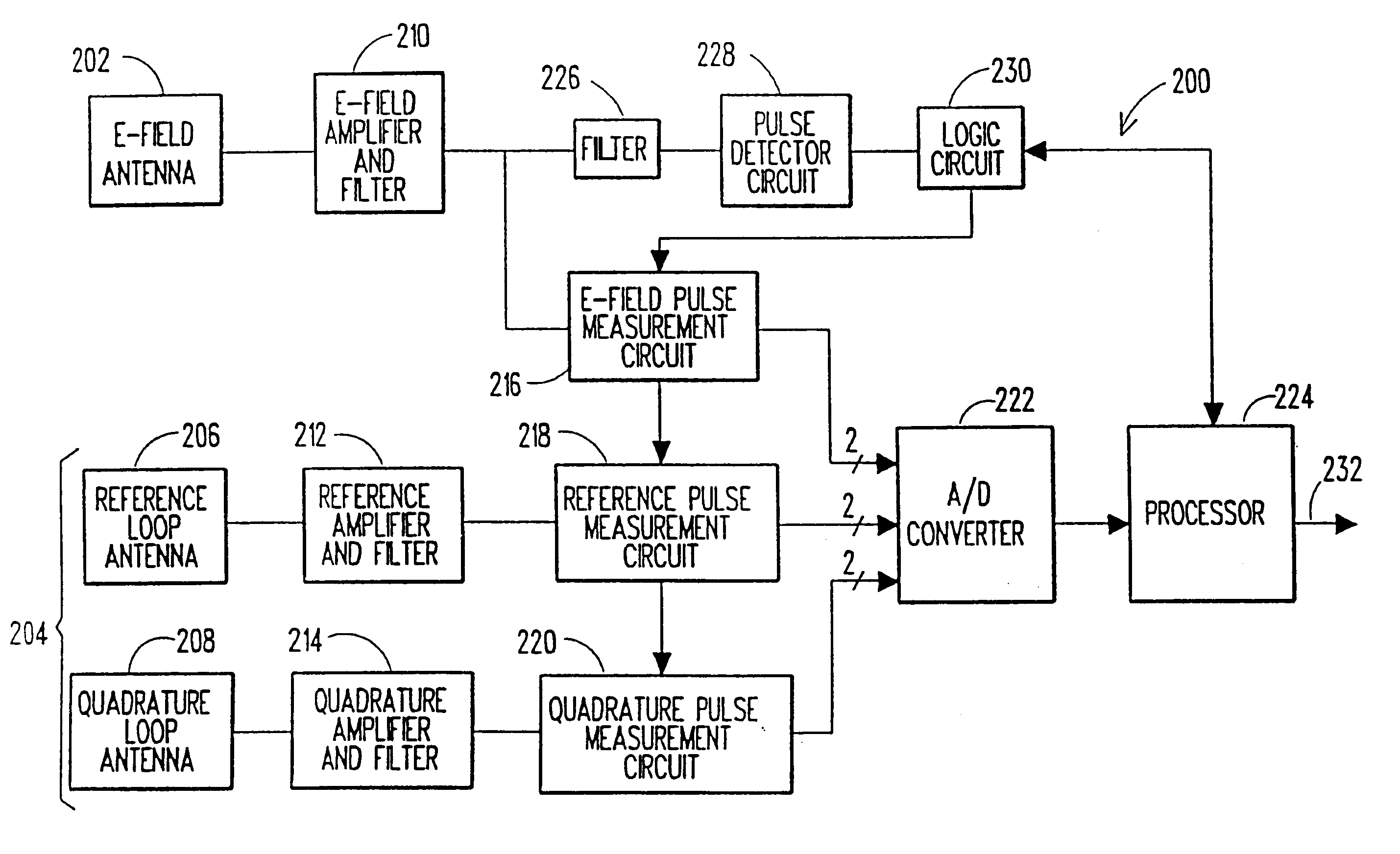
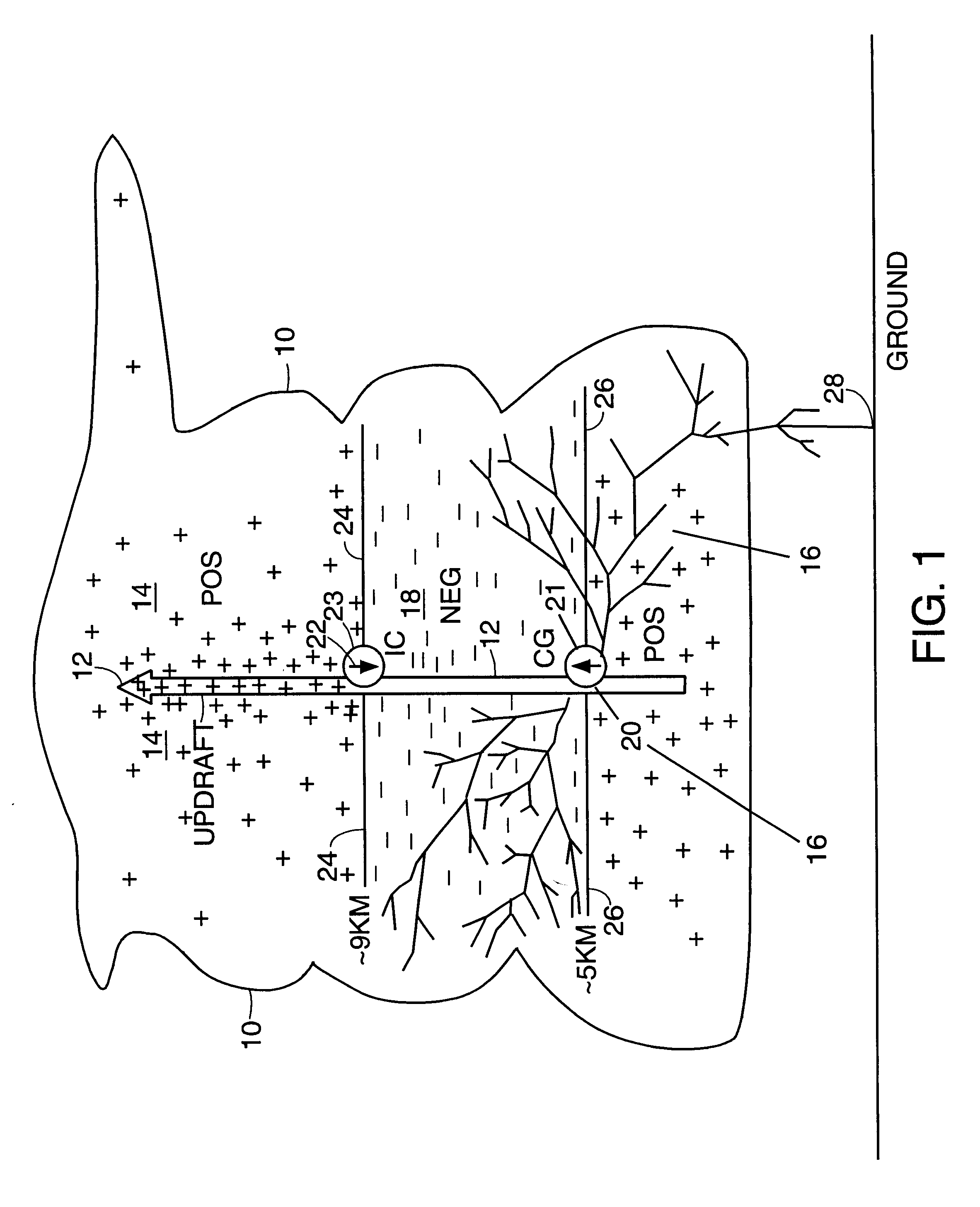
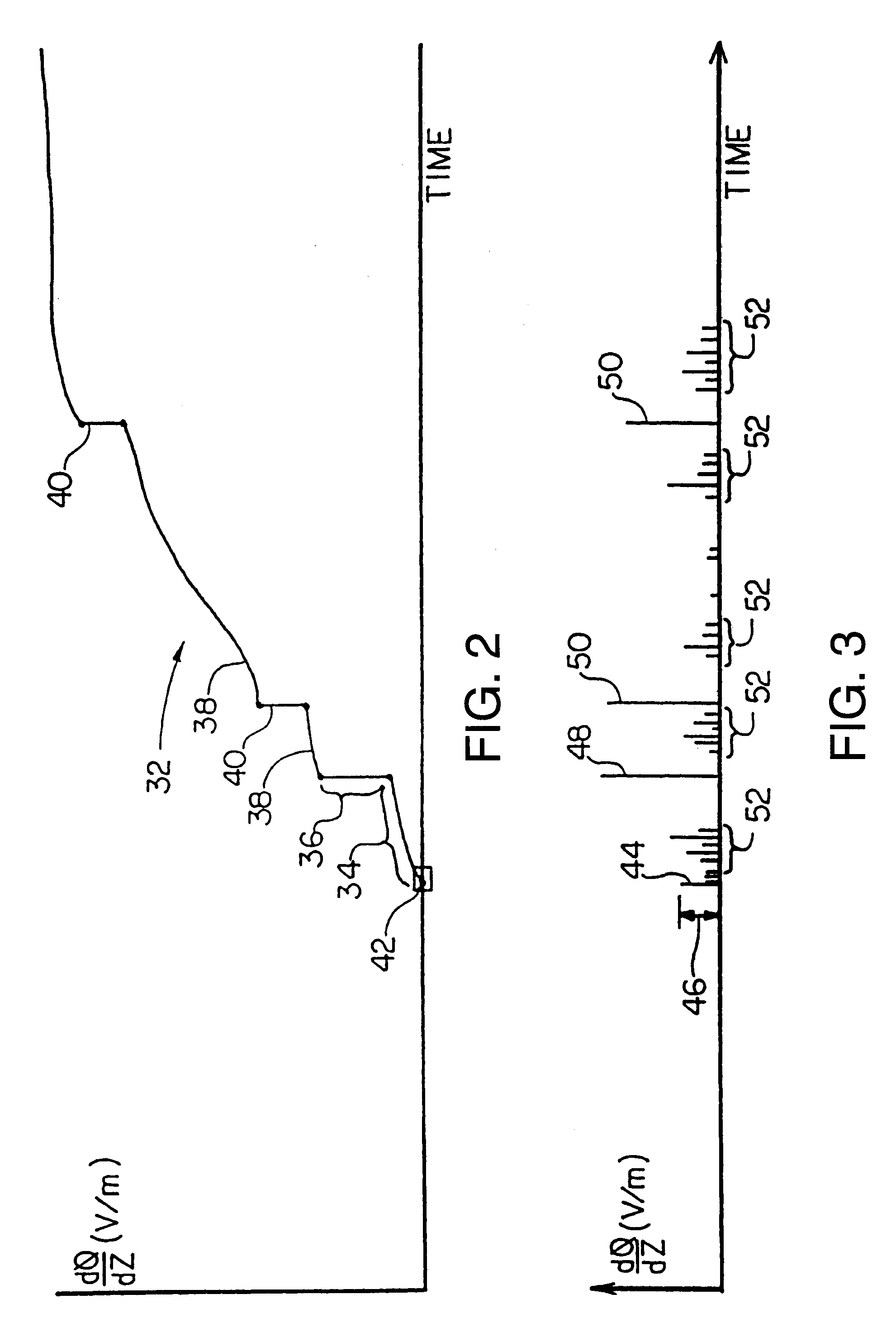
FIGS. 10-14 illustrate a lightning detection system having a single sensor. Prior single sensor lightning detection systems have been unable to accurately provide range data for lightning due in large part to lightning variations in intensity and direction. The lightning detection system of the present invention takes advantage of the known characteristics of an initial pulse of a lightning discharge to determine the location of the discharge source and to infer the altitude from differentiating between an IC and CG pulse In particular, the initial lightning discharge is vertical with respect to ground and has a known amplitude that falls off as a function of distance. The initial pulse also has a known duration of about one microsecond or less. Furthermore, IC and CG discharges are distinguishable by polarity. The single sensor system is adapted for placement on an airplane or ground.

An exemplary single sensor lightning detection system 200 includes an E field antenna 202 and a cro...


PUM


Abstract

A lightning detection system for detecting and locating an initial discharge of an initial leader stroke of a lightning flash. An initial lightning discharge produces a pulse that can be used to accurately detect lightning, and more particularly, the location of the initial lightning discharge. In one embodiment, at least three sensors detect and determine the location of the first pulses from initial lightning discharges using time difference of arrival information of the pulses at each of the three sensors. In another embodiment, a single sensor is used to determine the range of an initial lightning discharge from the amplitude of a corresponding initial detected pulse, and to determine the direction from a crossed loop antenna An alternative embodiment of a single sensor system determines a distance of a lightning event from a peak amplitude value derived from a pulse amplitude distribution. In a further embodiment, a lightning detection system provides enhanced lightning location by incorporating weather data from a weather radar with detected lightning information.

Description

FIELD OF THE INVENTIONThe invention relates generally to lightning warning systems, and more particularly to an early lightning warning system for detecting and processing initial lightning discharges.BACKGROUND OF THE INVENTIONLightning includes electrical discharges within a cloud, intracloud (IC) discharges, and cloud to ground (CG) discharges (total lighting. Lightning occurs when electrical fields within a cloud intensify as particles of opposite polarity collect at differing regions within the cloud. Typically, the electric field forms as a result of strong updrafts which carry monopolar positive charge aloft leaving negative space charge in a central or lower part of the cloud. Precipitation and downdrafts can also transport negative space charge downward. The updrafts as downdrafts further contribute to the electrification of the cloud particles. Lightning generally occurs near the location of these intense updrafts and downdrafts.Lightning begins with a an initial electrica...

Claims


Application Information

Patent Timeline
IPC IPC(8): G01S11/06G01S11/00G01R29/08G01S5/06G01S3/14G01S3/26H05F3/00G01S13/00G01S13/95G01S13/86G01S5/04G01S5/14G01W1/16G01S19/36
CPCG01R29/0842G01S3/26G01S5/06G01S11/06G01W1/16H05F3/00G01S5/04G01S13/86G01S13/95Y02A90/10
Inventor MARKSON, RALPH J.RUHNKE, LOTHAR H.
Owner STRATEGIC DESIGN FEDERATION W LLC
Why Eureka
Try Eureka