Use of a single-stage or multistage stirrer to prepare polymers

Inactive Publication Date: 2001-06-26
BASF AG
View PDF8 Cites 28 Cited by
  • Summary
  • Abstract
  • Description
  • Claims
  • Application Information

AI Technical Summary

Problems solved by technology

A disadvantage is that the stirrer shaft must have a relatively large diameter because of the bending moments which occur.
Introducing the stirrer from below into the reactor, on the other hand, reduces the mass of the stirrer but at the same time requires more complex sealing of the stirrer shaft as it penetrates the reactor floor.
In comparison with customary stirring techniques, such as the preparation and homogenization of solutions, two-phase liquid phase polymerization is accompanied by a number of particular problems that are particularly significant for the design of the reactor and for the mode of operation.
This leads to greater difficulty in mass transfer, heat dissipation, mixing and stirring owing to the increasing viscosity of the reaction mixture.
A further problem is the decrease in jacket cooling area in relation to volume as the size of the reactor vessel increases.
It is additionally known that, deposition of polymer on the walls and internals tends to occur particularly in dead zones in the reactor chamber.
It is known, indeed, that in zones of particularly high shear there is formation of coagulum structures which likewise lead to off-specification product and cont

Method used


Image

  • Use of a single-stage or multistage stirrer to prepare polymers
  • Use of a single-stage or multistage stirrer to prepare polymers
  • Use of a single-stage or multistage stirrer to prepare polymers

Examples


example 2

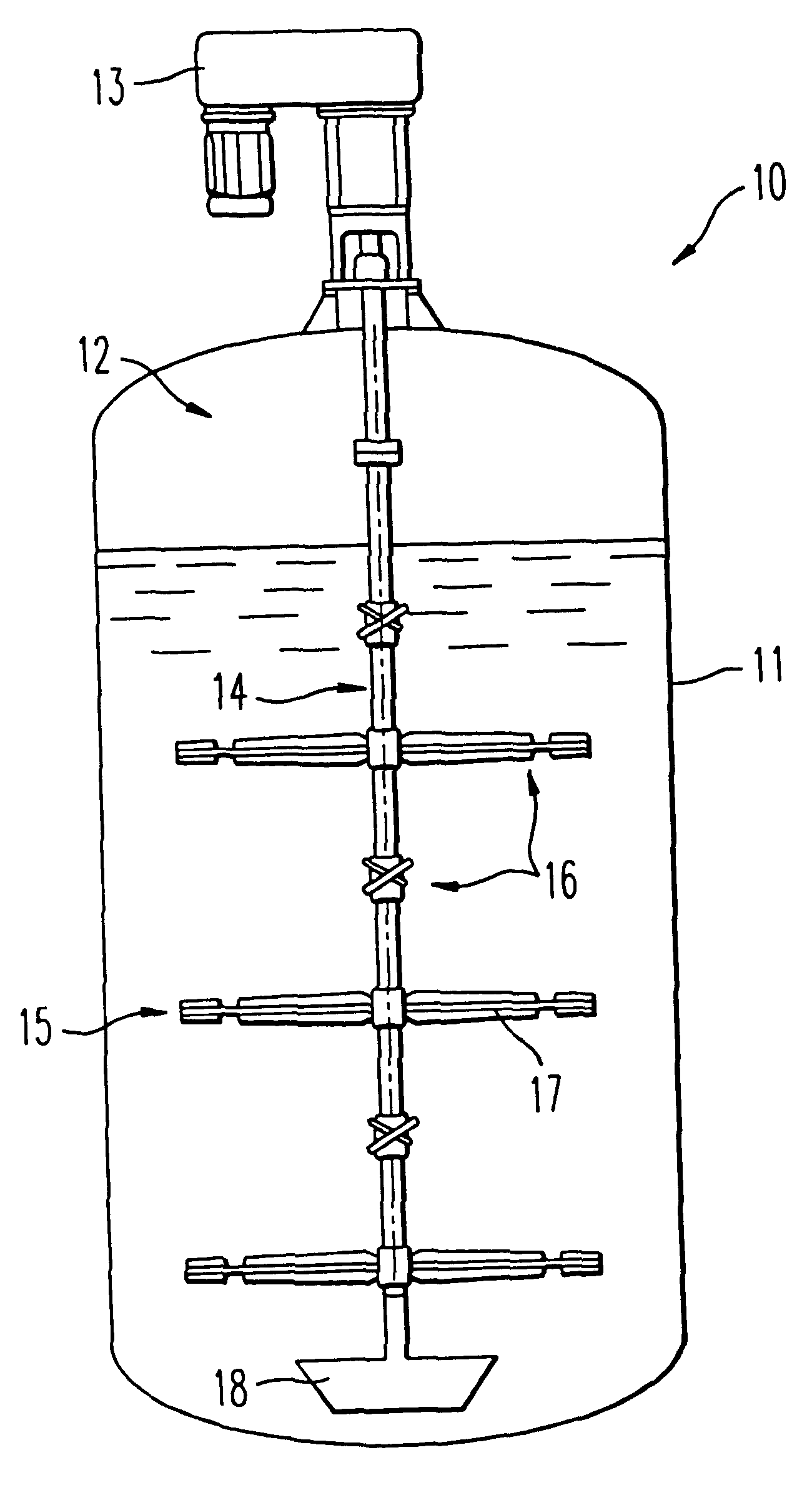
Example 1 is repeated in an 18 m.sup.3 reactor of the same construction (same height / diameter ratio and same cooling jacket), having a 4-stage MIG stirrer (d / D=0.85) with blade stages rotationally offset relative to one another by 90.degree.. The stirrer speed is raised to 40 rpm and the total cooling capacity is utilized. In this case the feed time of the monomer emulsion can be reduced to 180 min; the initiator solution is run in for 30 minutes longer as in Example 1. Subsequent procedure is as in the case of Example 1. A coagulum-free dispersion having a solids content of 55.4%, a pH of 7.5, an LT of 50%, a viscosity of 80 mPas and a content of fine coagulum of 0.001% is obtained. The particle size distribution (PSD) is tetramodal (see Tab. 1). There is no wall deposit. The use of a multistage stirrer permits the same amount of heat to be dissipated in a shorter time, reduces the formation of wall deposits and the content of fine coagulum, and leads to a reproducible PSD when 10 ...

example 3

Example 2 is repeated in the same reactor with the difference that the feed streams are fed in through the reactor floor and the stirrer speed is raised to 43 rpm. In this case, the feed time of the monomer emulsion can be reduced to 165 min. The initiator solution is again run in for 30 minutes longer. A coagulum-free dispersion having a solids content of 55.3%, a pH of 7.5, an LT of 49%, a viscosity of 78 mPas and a content of fine coagulum of 0.001% is obtained. The PSD is tetramodal (see Tab. 1). There is no wall deposit.

example 4

Example 2 is repeated in the same reactor with the difference that a feed stream consisting of acrylonitrile and butyl acrylate and a second, aqueous feed stream consisting of water, acrylic acid, emulsifiers and sodium persulfate (proportions as in Example 1) are fed into the reactor from below. The two streams are mixed shortly before entering the reactor. In this case the stirrer speed is raised to 45 rpm and the feed time is extended to 180 minutes. The aqueous feed stream is run in more slowly by 15 minutes. After complete addition, the batch is held at polymerization temperature for 2 hours more, cooled and filtered to remove coagulum. A dispersion with a solids content of 55.3% and a pH of 7.8 is obtained. The PSD and viscosity are not significantly different from that of Example 3.


PUM

PropertyMeasurementUnit
Fractionaaaaaaaaaa
Fractionaaaaaaaaaa
Fractionaaaaaaaaaa

Abstract

At least one single-stage or multistage stirrer which produces not only a tangential flow component but also an axial flow field is used in a stirred-vessel reactor in connection with the preparation of polymers by liquid phase polymerization.

Description

The invention relates to the use of a single-stage or multistage stirrer.DISCUSSION OF RELATED ARTThe preparation of polymers by liquid phase polymerization is customarily subdivided into bulk, solution, precipitation, suspension and emulsion polymerization, the latter two polymerization techniques differing from the others in that they start from an already two-phase initial mixture. The polymerization reaction is in this case conducted in a batch reactor, in a continuous flow pipe, in a cascade of stirred vessels or in a continuous stirred-vessel reactor. In this context it is the vessel reactors which have acquired the most importance in the chemical industry, since they permit very great flexibility in terms of operating conditions and mode of operation and can be adapted to virtually all process requirements. Stirred-vessel reactors are suitable for continuous and batchwise operation and possess broad scope for use, ranging from laboratory vessel to large-scale reactor. Stirred...

Claims


Application Information

Patent Timeline
IPC IPC(8): B01J19/20B01J19/18C08F6/00B01F7/00C08F2/00C08F2/01C08F2/16C08F2/18
CPCB01J19/18B01J19/20C08F6/006B01F7/00433B01J2219/00094B01J2219/00177B01J2219/00189B01J2219/185B01F27/1145
Inventor RUPANER, ROBERTLAWRENZ, SVENBAUER, GERHARDDOBBELAAR, JOHANNESNAHSTOLL, JURGENMUESELER, FRANZ-JOSEFFERBER, AXELHARTMANN, JURGENKELLER, PETERMEISTER, MARTINNEUTZNER, JOSEFREHMER, GERD
Owner BASF AG
Why Eureka
Try Eureka