Process gas decomposition reactor

Inactive Publication Date: 2001-07-17
GREENX
View PDF7 Cites 54 Cited by
  • Summary
  • Abstract
  • Description
  • Claims
  • Application Information

AI Technical Summary

Benefits of technology

The microwave energy from each of the transformers is directed to the helical induction structure from two microwave oscillator sources via the two cores. Ther

Problems solved by technology

Some scientists have predicted that foreseeable destruction of the ozone layer will cause increases in ultraviolet radiation with negative health effects, damage to certain crops and to plankton and the marine food web, with an accompanying increase in carbon dioxide due to the decrease in plants and plankton.
Secondly, these gases absorb atmosp

Method used


Image

  • Process gas decomposition reactor
  • Process gas decomposition reactor
  • Process gas decomposition reactor

Examples


Embodiment Construction

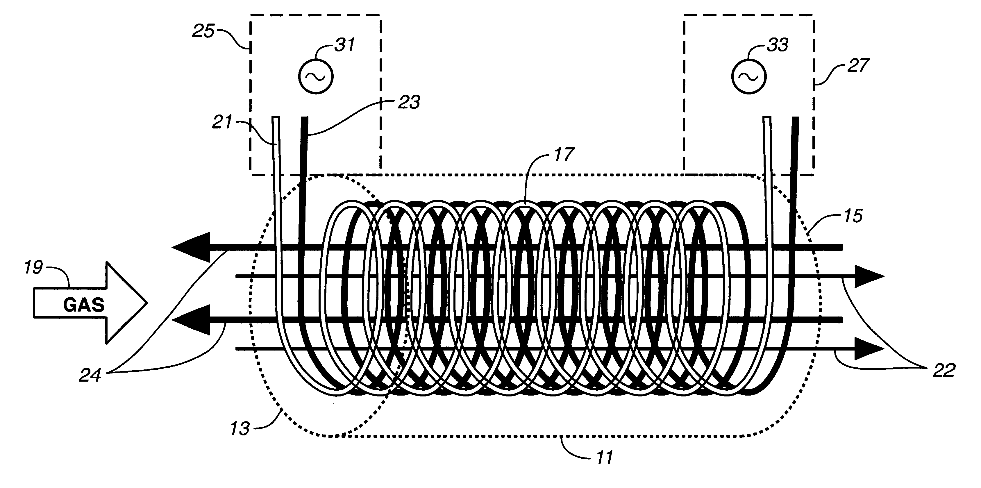
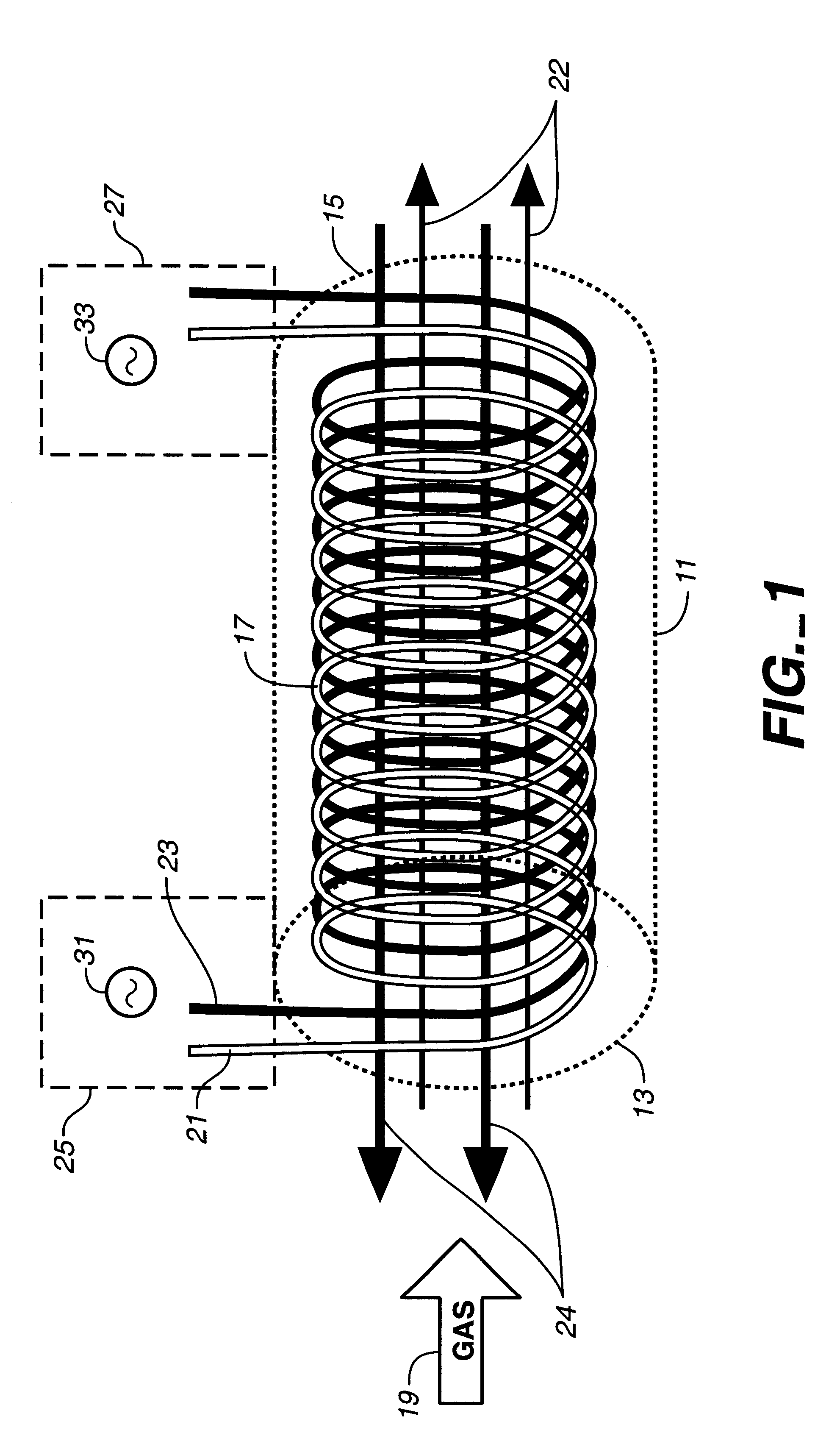
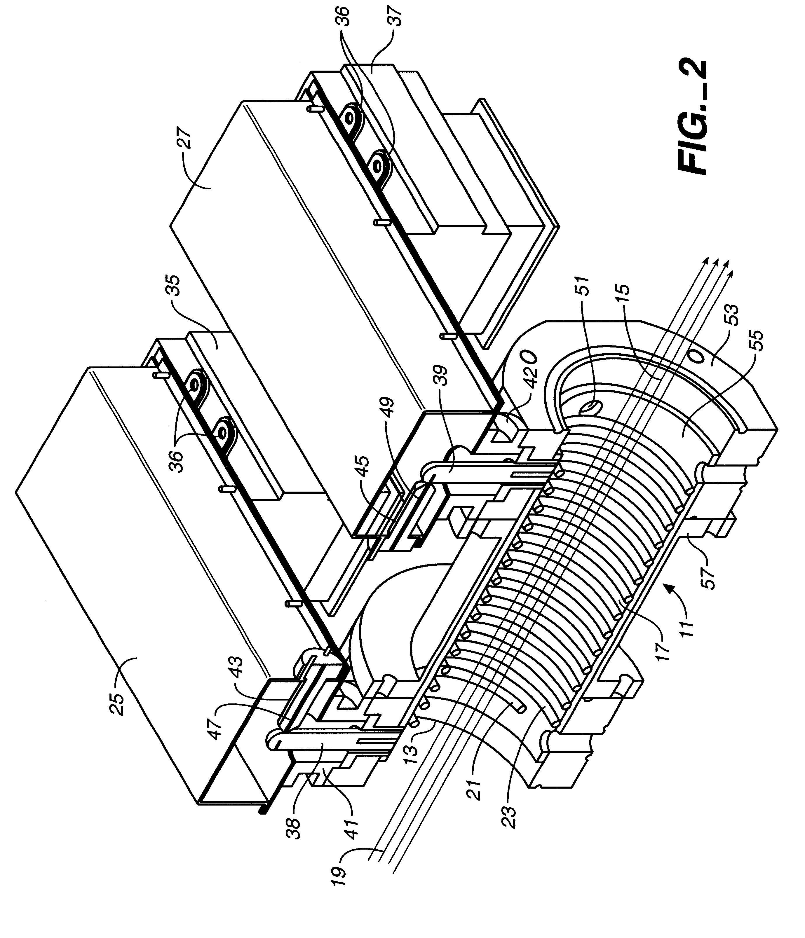
With reference to FIGS. 1 and 2 a chamber 11 is shown having a gas inflow port 13 and a gas outflow port 15. The diameter of input port 13 should match the diameter of the outlet port of a process tool so that a gas flow stream 19 will enter the inflow port 13 without generation of a significant back pressure. It is intended that the process gas decomposition reactor shown in FIGS. 1 and 2 be part of, or connected to, the process gas tools used in industry, particularly the semiconductor manufacturing industry.

The gas flow stream 19 flows into the central region 17 where field lines 22, arising from the first intertwined coil 21 cause restriction of motion of ions and electrons to the immediate vicinity of the field lines. Gases are ionized by collision with these electrons and ions, thereby causing PFCs and HFCs to decompose. A reactant gas or gases, such as hydrogen, oxygen or water vapor, is introduced into the chamber to facilitate formation of reactions with the decomposed cons...


PUM


Abstract

A process gas decomposition reactor featuring two intertwined helical coils surrounding a gas flow path. Each of the two coils is energized by a separate magnetron having an associated waveguide and an inductive structural element which couples the microwave energy into the coil. The magnetic flux lines from the coil serve to confine ions and electrons within the coil, causing collisions and hence ionization of gas entering a flow path through the coil. The gas, containing HFCs and PFCs is broken down by such collisions with ions and electrons within the gas plasma. The gas displaced at the end of the coil contains decomposition products from the HFCs and PFCs.

Description

TECHNICAL FIELDThe invention relates to a gas decomposition reactor and, more particularly, to a reactor for decomposing greenhouse gases emitted by semiconductor wafer processing tools.BACKGROUND ARTCertain organic gases known as perfluorinatedcarbons (PFCs) and hydrofluorocarbons (HFCs), emitted by industrial processes, particularly semiconductor process tools, trap infrared radiation in the atmosphere, contributing to the greenhouse effect. These gases can also decompose in the upper atmosphere where highly reactive fluorine and fluorine compounds are liberated. These interact and react with ozone, generally causing the ozone to become molecular oxygen and enter reactions forming stable compounds. There is a net removal of ozone from the atmosphere in the ozone layer, a region of the atmosphere from 18 to 48 km (12 to 30 mi) above the earth's surface. Some scientists have predicted that foreseeable destruction of the ozone layer will cause increases in ultraviolet radiation with ...

Claims


Application Information

Patent Timeline
IPC IPC(8): B01J19/12H05B6/78
CPCB01J19/126H05B6/806H05B6/782H05B6/802B01J2219/0871B01J2219/0875B01J2219/0894B01J2219/1296H05B2206/046B01J2219/1227
Inventor MINAEE, BRUCE
Owner GREENX
Why Eureka
Try Eureka