
Composite sheet comprising a non-woven fabric and a film

a non-woven fabric and film technology, applied in the field of composite sheets comprising non-woven fabrics and films, can solve the problems of increasing the weight and cost of products, not having a good touch, and not looking like high-quality products, and achieves the effects of low melting component, high melting point component, and easy production

Inactive Publication Date: 2001-08-07
JNC CORP
View PDF14 Cites 37 Cited by
  • Summary
  • Abstract
  • Description
  • Claims
  • Application Information

AI Technical Summary

Benefits of technology

As the thermoplastic crystalline film used in the present invention, the well known thermoplastic crystalline film can be used. Typical examples of the thermoplastic crystalline film include: a linear low density polyethylene film, a high density polyethylene film, polypropylene film, polyethylene terephthalate film or the like. These thermoplastic crystalline films are the most popular and can easily be obtained at a low price, but the thermoplastic crystalline film is not limited to them alone. A multi layered film may be used, but it is advantageous to use mono layer films from the view point of the cost. The reason for using a crystalline film instead of other thermoplastic films is: the crystalline film has a relatively high strength and suffers little damage (little generation of holes) during the thermal adhesion.
Examples of the non-woven fabrics comprising a thermoplastic conjugated fiber of the present invention may include: a non-woven fabric comprising conjugated fiber (staple fiber) made by a carding process; a non-woven fabric comprising conjugated fiber (staple fiber) made by an air-laid method; a non-woven fabric comprising conjugated fiber (staple fiber) made by a wet method for paper making, and a non-woven fabric comprising conjugated fiber (staple fiber) made by a melt-blowing process; and a non-woven fabric comprising conjugated fiber (filament, more specifically a continuous filament) made by a spun bond method. In particular, a non-woven fabric comprising filaments is preferably used since it has a high strength and little fuzz. Especially, the non-woven fabric made by the spun bond method is preferable, since non-woven fabrics can be manufactured without application of fiber spinning oil agents, a stretching step is not conducted after the solidification of a melt spinning filament spun out of the spinneret, and crystalline orientation is less likely to occur in the filaments as compared with staple fibers made by a method having a stretching step, so that such filaments are easily bonded to a thermoplastic crystalline film. Moreover, the spun bond method is preferable since the cost is reasonable.
As the conjugated fiber used in the present invention, a sheath and core type conjugated fiber or a side-by-side type conjugated fiber is used. The sheath and core type conjugated fiber includes an eccentric core and sheath type conjugated fiber. In the sheath and core type conjugated fiber, a low melting point component is used for a sheath, and a high melting point component is used for a core. In particular, the use of an eccentric sheath and core type conjugated fiber or side-by-side type conjugated fiber makes it possible to produce a crimped fiber, thus preferably producing a non-woven fabric having a high bulkiness and a good hand feeling. In the side-by-side type conjugated fiber, the ratio of the low melting point component to the high melting point component in the cross section may be 1:1. Needless to say, one component may account for more than another component in the cross section. The volume ratio (this corresponds to the area ratio when a cross section of the fiber is considered) of the low melting point component to the high melting point component is usually 10:90 to 90:10. More preferably, the ratio is 30:70 to 70:30.
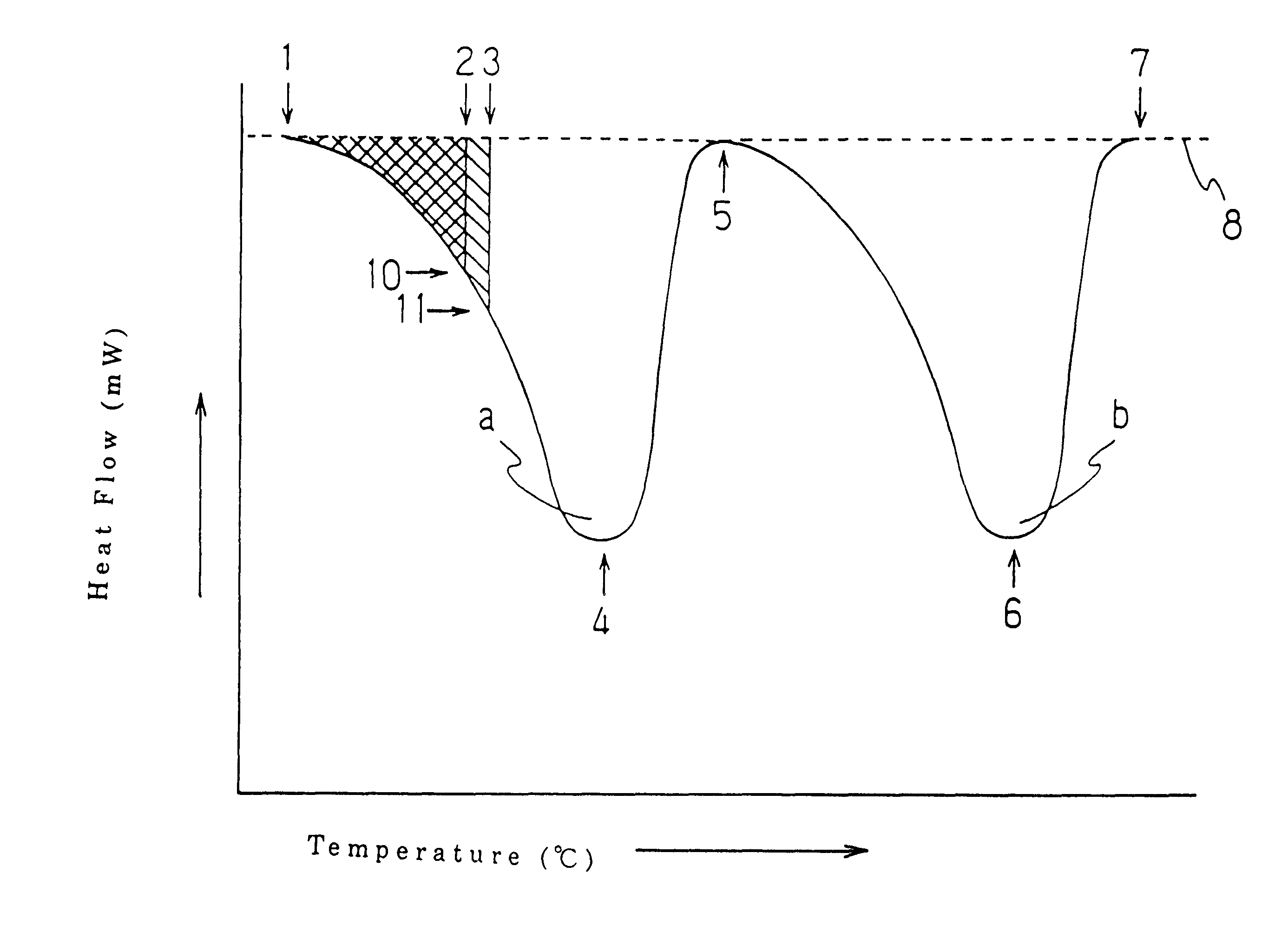
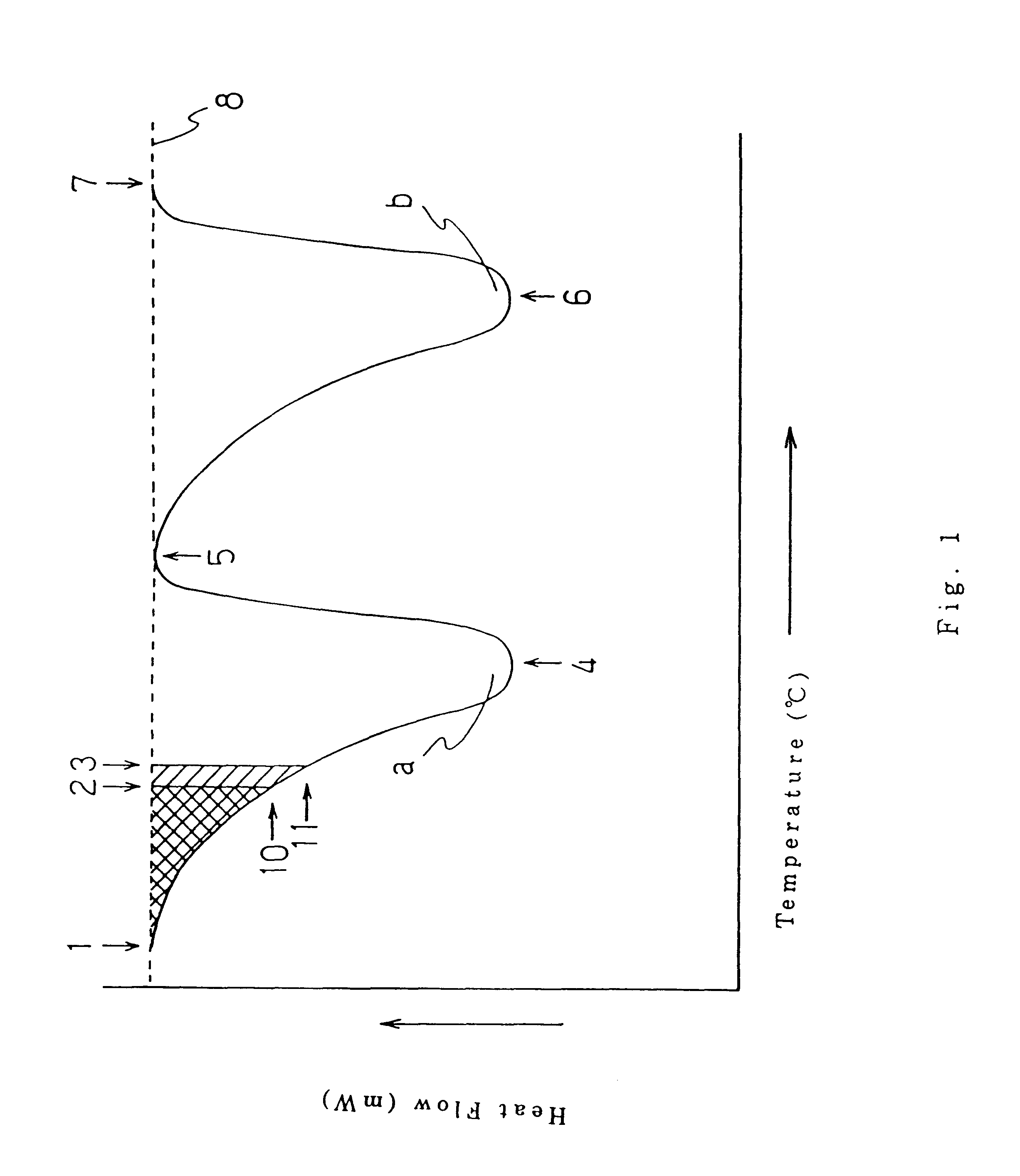
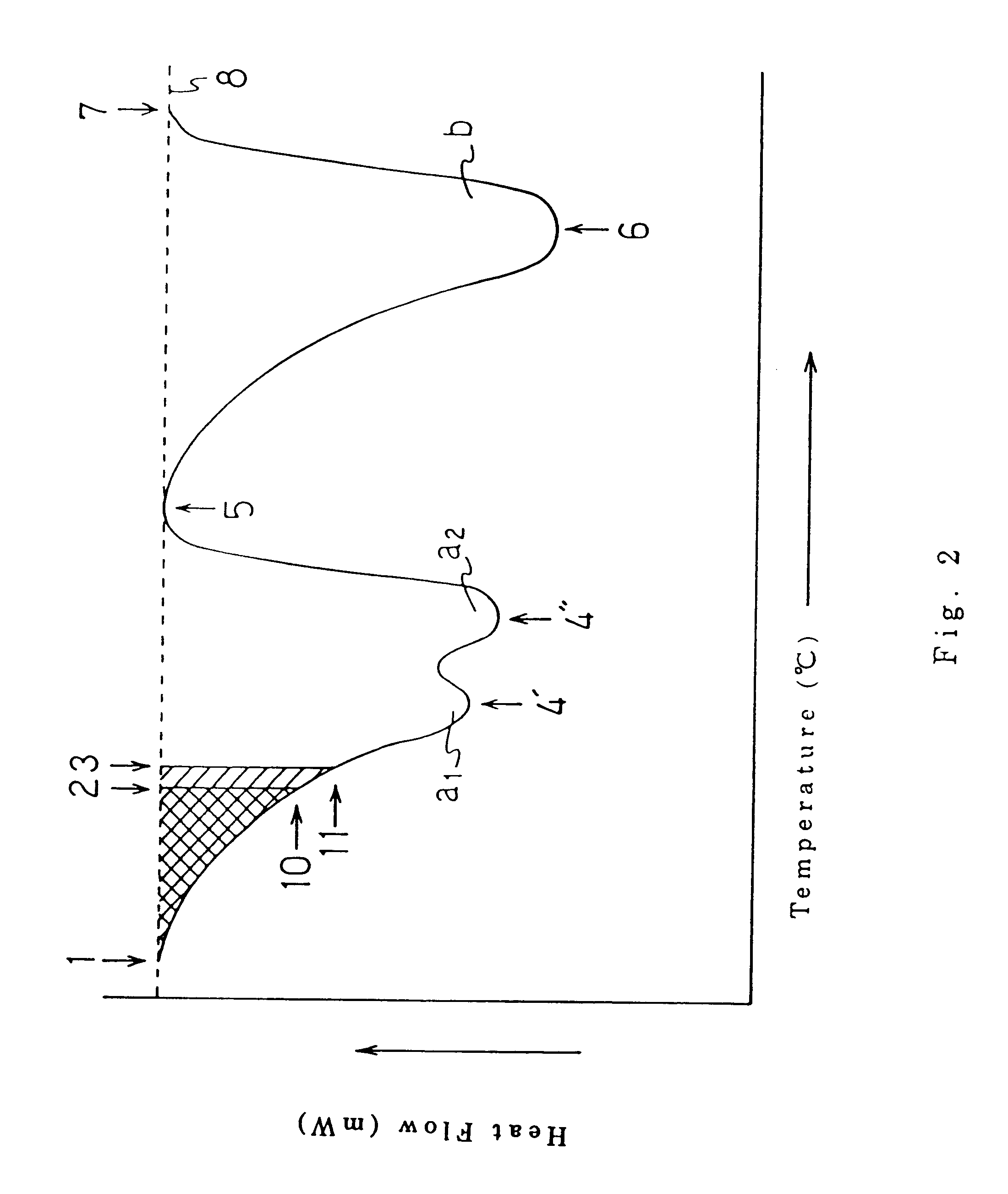
More preferably, as a combination of a thermoplastic conjugated fiber and a film, in addition to the above mentioned conditions, the combination which satisfies the following conditions is selected: an endothermic peak of the thermoplastic conjugated fiber of an entire conjugated fiber evaluated by DSC is separated into an endothermic peak of a low melting point component and an endothermic peak of a high melting point component with respect to the base line of the endothermic peak curve, and the temperature of the position corresponding to 20% of the area from the side of the melting starting point of the endothermic peak of the low melting point component of the conjugated fiber is between the melting starting point and the melting completion point of the endothermic curve of the thermoplastic crystalline film from DSC analysis. If the combination where such conditions are further added is selected, the thermal adhesion can easily be conducted under the temperature conditions in which the thermal damage such as a relaxation of orientation of high melting point component is less likely to occur, thus of a resin for the a being preferable.
In a case where a non-woven fabric is obtained by the use of conjugated staple fiber, a conjugated fiber comprising the combination of the low melting component and the high melting point component can easily be obtained, since they are commercially available. The conjugated fiber produced by the spun bond method is commercially available and can easily be obtained. Moreover, a non-woven fabric can be made of a staple fiber spun from the conjugated fiber by the use of a spinneret, and a non-woven fabric can be directly made from the conjugated fiber by the melt-blow method. Moreover, a non-woven fabric directly made of filament by the spun bond method or the like by applying a means for manufacturing a conjugated filament can further be obtained.
In the present invention, it is preferable that the combination of a film and a non-woven fabric wherein non-woven fabric comprising a staple fiber and / or a filament comprising a conjugated fiber comprising a low melting point component and a high melting point component is used and the low melting point component of the non-woven fabric is softened and adhered at the temperature that does not cause thermal damage to the film. Therefore, in addition to the above mentioned conditions, the combination between a film and a non-woven fabric, wherein the melting point of the low melting component of the thermoplastic conjugated fiber is lower than the melting point of the thermoplastic crystalline film is more preferable.

Problems solved by technology

However, in a case where thermoplastic resin films are used for the above mentioned water-proof substrates, there are some problems.
In other words, such water-proof substrates give a cool touch to users' skin; are not cloth-like in appearance due to glistening, so that they do not look like high quality products; and do not have a good touch.
In order to laminate non-woven fabrics by the use of a hot melt resin, an apparatus for spraying a hot melt resin, a hot melt type adhesive comprising a low temperature melting resin that does not cause thermal damage to a film and a non-woven fabric are required, thus increasing the weight and the cost of the products.
Moreover, a large area for adhering is required to ensure an excellent adhesion between a film and a non-woven fabric, so that it is difficult to apply hot melt resins as an adhesive agent inconspicuously and uniformly.

Method used


Image

  • Composite sheet comprising a non-woven fabric and a film
  • Composite sheet comprising a non-woven fabric and a film
  • Composite sheet comprising a non-woven fabric and a film

Examples


example 2

A commercially available composite spun bond non-woven fabric composed of polyethylene terephthalate (the melting point from DSC analysis was 260.degree. C.) as a core component and high density polyethylene (the melting point from DSC analysis was 129.degree. C.) as a sheath component at the volume ratio of 60:40 ("ELEVES," the product of UNITIKA, LTD, was used. The temperature of the position corresponding to 10% of the area from the side of the melting starting point of the endothermic peak of an entire conjugated fiber evaluated by DSC was 115.degree. C., and the temperature of the position corresponding to 20% of the area from the side of the melting starting point of the endothermic peak of the low melting point component of the conjugated fiber was 120.degree. C. The basis weight of a non-woven fabric was 20 g / m.sup.2. The fabric was preliminarily heated by using a far infrared radiation heater (the temperature of the surface of the non-woven fabric measured by the use of a h...

example 3

A conjugated fiber composed of polypropylene (the melting point from DSC analysis was 160.degree. C.) as a core component and linear low density polyethylene (the melting point from DSC analysis was 122.degree. C.) as a sheath component at the volume ratio of 50:50 was made by the melt spinning method by the use of an eccentric core and sheath type spinneret. The spinneret had 120 circular spinning holes with a diameter of 0.4 mm. The fibers spun out of the spinneret were introduced into an air sucker where stretching was conducted. Thus, a group of filaments were produced. Then, a group of filaments discharged from the air sucker were made to pass between a couple of vibrating wing-like tool for an opening. A group of the opened filaments was collected on an endless belt conveyor having a suction apparatus on its back face to form filament webs. At this time, the fineness of the filament was controlled to 2.2 d / f by varying the stretching rate of the air sucker. The resultant eccen...

examples 4 and 5

A conjugated filament composed of a core component and a sheath component at the volume ratio of 50:50 was made by the melt spinning method by the use of a concentric core and sheath type spinneret and made into conjugated filament web with a fineness of 3.5 d / f. Instead of using the low melting point component resin of the conjugated filament used in Example 3, an ethylene-octene copolymer comprising 2.0 wt. % of 1-octene and ethylene-octene copolymer comprising 13.4 wt. % of 1-octene (the melting points evaluated by DSC were respectively 121.degree. C. and 100.degree. C.) were used as the low melting point component resins in Examples 4 and 5. The temperatures of the position corresponding to 10% of the area from the side of the melting starting point of the endothermic peak of an entire conjugated fiber evaluated by DSC were respectively 92.degree. C. and 73.degree. C., and the temperatures of the position corresponding to 20% of the area from the side of the melting starting poi...


PUM

PropertyMeasurementUnit
Fractionaaaaaaaaaa
Fractionaaaaaaaaaa
Linear densityaaaaaaaaaa

Abstract

A composite laminated sheet comprises a thermoplastic crystalline film and a non-woven fabric having a thermoplastic conjugated fiber comprising the low melting point component and the high melting point component, in which the difference in the melting point between the low melting point component and the high melting point component is not less than 10° C.; the difference in the melting point between the thermoplastic crystalline film and the low melting point component of the conjugated fiber is not more than 30° C.; and the temperature of the position corresponding to 10% of the area from the side of the melting starting point of the endothermic peak of an entire conjugated fiber evaluated by DSC is between the melting starting point and the melting completion point of the endothermic peak of the film evaluated by DSC. According to the present invention, a composite sheet is provided in which a non-woven fabric and a film are adhered without adhesive agents, the appearance is excellent, and the adhesive strength between the non-woven fabric and the film is high. Consequently, the composite sheet of the present invention can be used for a water-proof sheets, for example, paper diapers or sanitary napkins or the like.

Description

The invention relates to a composite sheet comprising a film and non-woven fabric having softness and an excellent touch (hereinafter, a laminated non-woven fabric sheet will be used for an abbreviation). More particularly, it relates to a laminated non-woven fabric sheet combining a non-woven fabric and a film, which is useful for water-proof substrates (water impermeable substrates) of paper diapers, sanitary napkins or the like.Hitherto, films comprising a thermoplastic resin have been used as water-proof substrates of paper diapers, sanitary napkins or the like. However, in a case where thermoplastic resin films are used for the above mentioned water-proof substrates, there are some problems. In other words, such water-proof substrates give a cool touch to users' skin; are not cloth-like in appearance due to glistening, so that they do not look like high quality products; and do not have a good touch. In order to solve the above mentioned problems, that is, to provide a high qua...

Claims


Application Information

Patent Timeline
IPC IPC(8): B32B27/12D04H13/00B32B5/02D01F8/06D04H3/007D04H3/147D04H3/153
CPCD04H13/007B32B27/12B32B5/022B32B27/32B32B2262/0253B32B2307/724B32B2323/043B32B2323/10B32B2555/02Y10T442/637Y10T442/641Y10T442/674Y10T442/678
Inventor NOMA, TAKESHIHORIUCHI, SHINGOTSUJIYAMA, YOSHIMI
Owner JNC CORP
Learn More