
Thermal pest control

a technology of pest control and thermal insulation, applied in the direction of lavatory sanitory, fumigators, chemicals, etc., can solve the problems of inability or too expensive to wrap buildings in tent foils, inability to use food processing plants, and inability to use process

Inactive Publication Date: 2001-08-28
BINKER MATERIALSCHUTZ
View PDF33 Cites 57 Cited by
  • Summary
  • Abstract
  • Description
  • Claims
  • Application Information

AI Technical Summary

Benefits of technology

The primary object of the present invention is to provide a process in which thermal pest control can be carried out in mills or other food-processing plants or food warehouses economically and effectively, and these processes may optionally also be employed combined with fumigation processes without, e.g., increased losses of gas or temperature drops occurring during the treatment.
Due to the gas-tight design of the separation 17 between the combustion chamber 13 and the heat exchanger chamber 8, no toxic fumigant, which was fed from the storage cylinder 4 into the room 1 being treated, will enter the combustion chamber 13. Due to the separation 17, no fumigant will be lost to the environment via the heater, either. In addition, thanks to the separation 17, the fumigant does not enter the burner 12 or the combustion chamber 13. Thermal decomposition of the fumigant is ruled out as a result. Corrosion due to predominantly acid combustion gases or decomposition products formed due to thermal decomposition is also avoided. After the end of a sufficient exposure time, the heater is switched off, and the room 1 being treated can be ventilated. The production process can be continued and the treated room 1 can be used again for its intended purpose.

Problems solved by technology

After a correspondingly long exposure time, the pests in the rafters are dead.
The wrapping of the buildings in tent foils is not possible or too expensive in the case of large objects, such as mills or large food-processing plants.
The combustion gases are disadvantageously introduced into the room being treated; this process cannot be used in food-processing plants.
The energy consumption is very high due to the relatively low efficiency of the electric heater, and mills with large room space can be heated up for pest control only if a block-type thermal power station is additionally available.
However, the hot steam may precipitate on cooler parts and damage due to moisture may thus occur in the mill.
The electric heaters consume a very large amount of energy, and they are therefore sometimes replaced with gas-heated furnaces.
In addition, this process has the drawback that the room to be treated cools more or less rapidly during the gas exposure time after the gas-heated burners have been switched off (Fumigation and Pheromones Workshop, West Lafayette, Ind., U.S.A., 1996, with practical demonstration of the process by D. and J. Mueller).
This leads to a loss of effectiveness during the process, because the pests breath in the phosphine substantially more rapidly at higher temperatures.
Problems also occur in the case of the use of carbon dioxide as a fumigant with the simultaneous heating of the atmosphere in the room being treated by means of oil- or gas-heated burners.
An overpressure is also generated in the room being treated due to the combustion process, because additional gases are introduced into the room being treated, so that the sealing needed for the fumigation may be damaged and greater losses of gas or heat may occur.

Method used


Image

  • Thermal pest control
  • Thermal pest control

Examples


example 2

A hulling mill is infested with flat grain beetle as well as Plodia interpunctella and Ephestia kuehniella. All openings, doors and large cracks in the wall of the mill are sealed in a gas-tight manner. Processing machines containing milling residues, which are likewise infested with, e.g., moth eggs, are accommodated in the attic of the mill. These machines also must be subjected to the pest control.

The attic of the mill already has a temperature of about 32.degree. C. due to exposure to sunlight, but only a temperature of 16.degree. C. can be measured on the first floor.

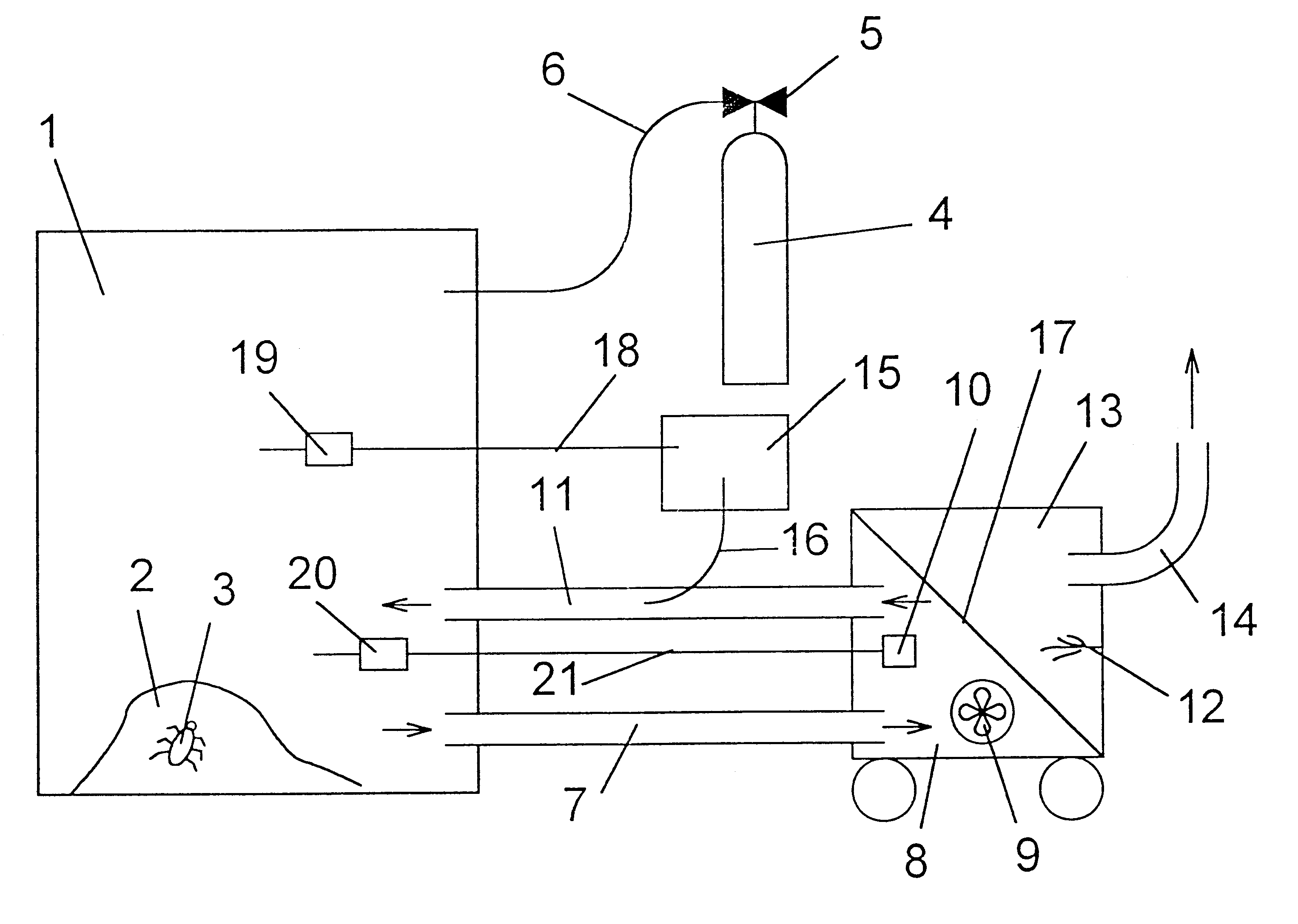
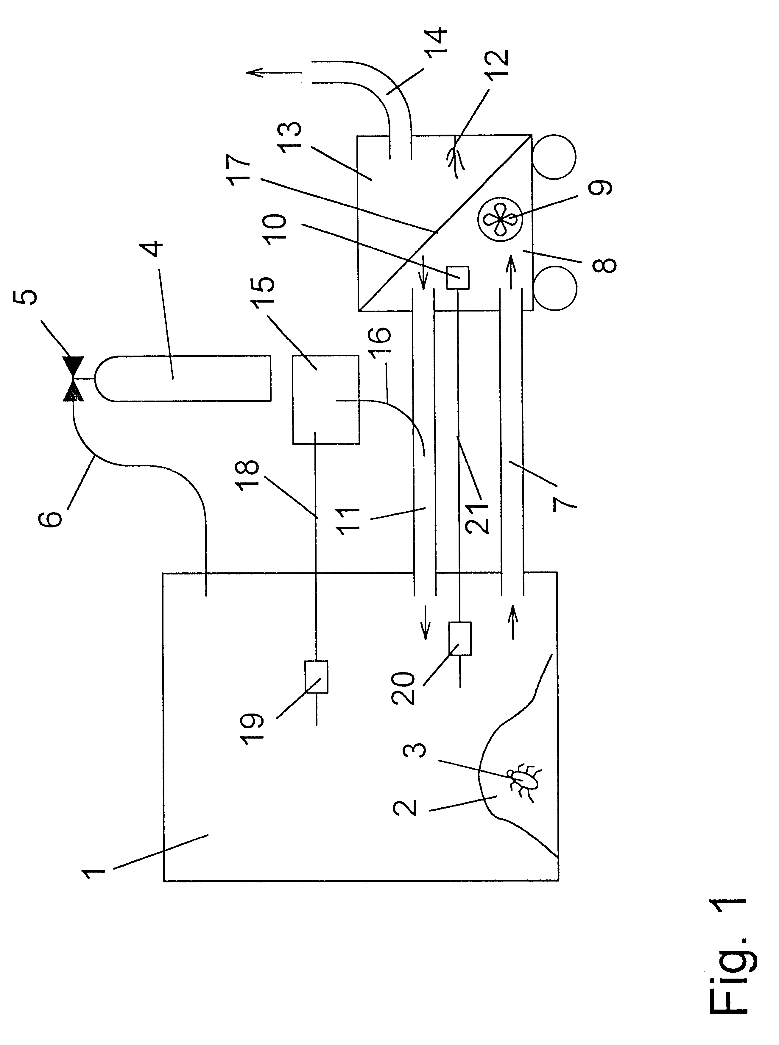
Test insects in cages are introduced in various areas of the mill. The cages also contain insect brood. Hot air is introduced into the hulling mill by means of a heater according to FIG. 1 via the heat exchanger with separate flue gas routing. A target temperature of about 25.degree. C. is sought to be reached in the mill. This temperature is reached in as little as 4 hours. All wall surfaces, objects, machines, wo...

example 3

A flour mill is infested by flour beetle and Ephestia elutella (a moth species). The mill is sealed in a sufficiently gas-tight manner and hot air is then introduced into the mill by means of a heater according to FIG. 1 at a starting temperature of 18.degree. C. The temperature in the mill is increased to 30.degree. C., doing so at a heat-up rate of 4.degree. C. per hour. Stresses on the furnishings and machines of the mill are avoided as a result. When a temperature of 30.degree. C. has been reached, this temperature is maintained at a constant value for about 1 hour and sulfuryl fluoride is then introduced into the mill from a storage tank. The sulfuryl fluoride concentration is maintained at a constant value of 35 g / cbm, the heater having been switched off already shortly before the introduction of the sulfuryl fluoride. The temperature in the mill drops to the initial temperature within 48 hours and the mill is then ventilated. All pests are dead, and no reinfestation can be se...


PUM


Abstract

In a process for thermal pest control, a fuel-operated heater with separate flue gas routing is used to heat up a space to be treated. Fumigants may be additionally introduced into the air of the space to be treated, especially if the combustion chamber 13 of the heater is separated from the heat exchanger chamber 8 of the heater in a gas-tight manner. The process is particularly suitable for disinfecting mills and food-processing plants.

Description

The present invention pertains to the control of pests mainly in the protection of stored products or in food-processing plants by means of heat.Oil- or gas-heated burners have been used in Denmark for a rather long time for controlling Hylotrupes bajulus in roofs. Oil or gas is burned and the heat released in the process heats air, which is introduced with the combustion gases into the infested roof truss. After a correspondingly long exposure time, the pests in the rafters are dead. Similar processes are also used to control termites and cockroaches in the U.S.A. The buildings are wrapped in foils or tarpaulins at the same time in this process in order to keep the heat loss as low as possible. The wrapping of the buildings in tent foils is not possible or too expensive in the case of large objects, such as mills or large food-processing plants.WO 92 / 00173 describes a process from the Netherlands, in which the heated air in the room being treated is additionally maintained at a min...

Claims


Application Information

Patent Timeline
IPC IPC(8): A01M17/00A01M19/00
CPCA01M17/008A01M13/003
Inventor BINKER, GERHARDBINKER, JOACHIM
Owner BINKER MATERIALSCHUTZ
Features
  • Generate Ideas
  • Intellectual Property
  • Life Sciences
  • Materials
  • Tech Scout
  • Unparalleled Data Quality
  • Higher Quality Content
  • 60% Fewer Hallucinations
Learn More