
Apparatus and method of determining a link status between network stations connected to a telephone line medium

Inactive Publication Date: 2001-09-18
GLOBALFOUNDRIES INC
View PDF4 Cites 79 Cited by
  • Summary
  • Abstract
  • Description
  • Claims
  • Application Information

AI Technical Summary

Benefits of technology

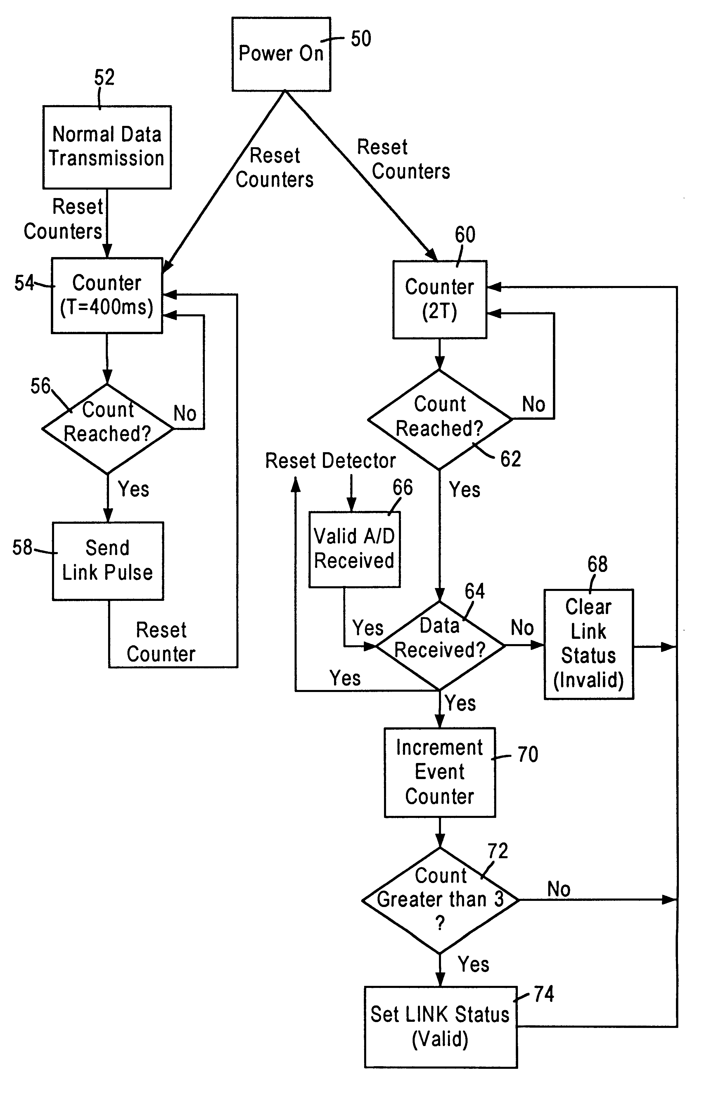
According to one aspect of the present invention, a method in a first network station enables detection of a link status with a second network station connected to a telephone line medium. The method includes determining a presence of a frame on the telephone line medium from the second network station within a prescribed interval. The method also includes setting the link status to an invalid state based on the determined absence of the frame within the prescribed interval. The detection of a transmitted frame on the telephone line medium enables the first network station to determine the link status based on the reception of the transmitted frame within a prescribed interval. If the frame is not detected within the prescribed interval, then the first network station sets the link status to an invalid state. In addition, the transmitted frame may be either a data frame, or a link frame having a length less than the minimum frame length. Use of a link frame having a length less than a minimum data frame length enables a physical layer transceiver to process the received link frame as if it was a data frame, by sending the link frame to the media access controller. Since the link frame is less than the minimum data frame length, the media access controller will discard the link frame as a runt frame, without wasting system resources in the receiving network station. Hence, a network station may reliably determine a link status with minimal disruption in network throughput, and while avoiding disruption of system resources in a network station.
Another aspect of the present invention provides a method in a network having a first network station, a second network station, and a telephone line medium for communication between the first and second network stations. The method includes transmitting by the first network station a link frame, having a length less than a minimum length of a data frame, onto the telephone line medium a first prescribed interval following transmission of the data frame by the first network station. The method also includes, in the second network station, determining a presence of the transmitted link frame on the telephone line medium within a second prescribed interval, and setting the link status to an invalid state based on the determined absence of the link frame within the second prescribed interval. The transmission of the link frame by the first network station having a length less than a minimum length of data frame enables the physical layer transceivers of other network stations to detect the link frame and thereby determine the presence of other stations on the network. Use of a link frame having a length less than the minimum data frame length also ensures that the link frame will not be processed by the other network stations, since the link frame will be classified as a runt packet and thereby discarded. Transmission of the link frame within a first prescribed interval following transmission of the data frame by the first network station also ensures that the link frame is transmitted during idle intervals, enabling the network stations to determine the link integrity without affecting network throughput.

Problems solved by technology

However, telephone lines are inherently noisy due to spurious noise caused by electrical devices in the home, for example dimmer switches, transformers of home appliances, etc.
In addition, the twisted pair telephone lines suffer from turn-on transients due to on-hook and off-hook and noise pulses from the standard POTS telephones, and electrical systems such as heating and air conditioning systems, etc.
Hence, the 10 BASE-T technique of sending link pulse cannot be used in a home networking environment, since the link pulses cannot be distinguished from noise signals inherently present in home networking environments.

Method used


Image

  • Apparatus and method of determining a link status between network stations connected to a telephone line medium
  • Apparatus and method of determining a link status between network stations connected to a telephone line medium
  • Apparatus and method of determining a link status between network stations connected to a telephone line medium

Examples


Embodiment Construction

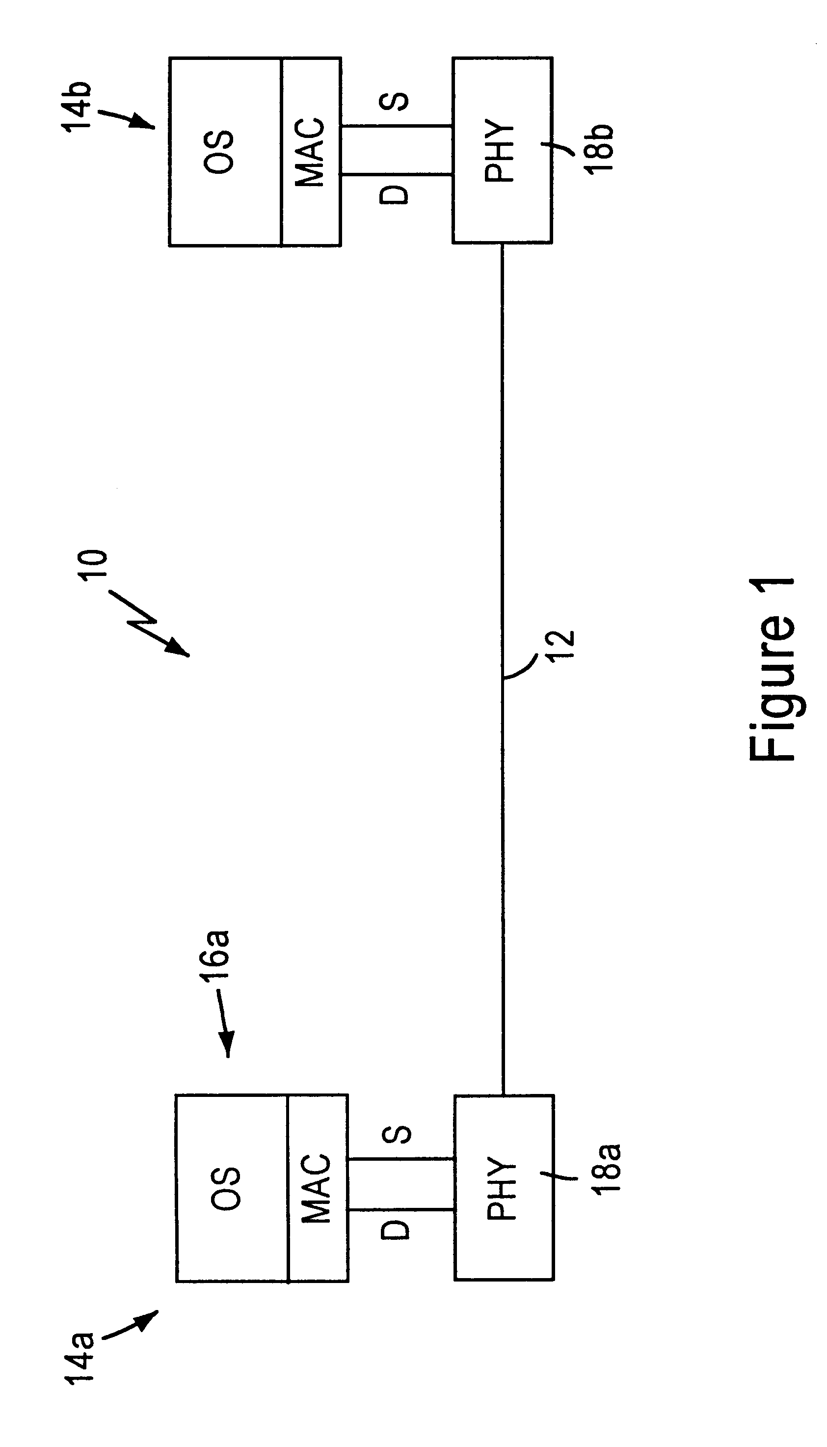
FIG. 1 is a block diagram of a network 10 for transmission of data in a home networking environment according to an embodiment of the present invention.

The network 10 includes a telephone line medium 12, specifically a twisted pair medium, and network stations 14 configured for sending and receiving a link packet and a data packet on the telephone line medium 12, described below. The telephone line medium 12 includes a plurality of branch connections (not shown) to interconnect telephones, facsimile machines, etc., to a telephone network interface, for connection to a public switched telephone network. The term "home networking environment," however, refers to use of the twisted pair medium 12 within a subscriber premises. Hence, the network 10 operates independently from telephony-related services provided by the public switched telephone network.

As shown in FIG. 1, each network station 14, for example a personal computer or intelligent consumer electronics device, includes an oper...


PUM


Abstract

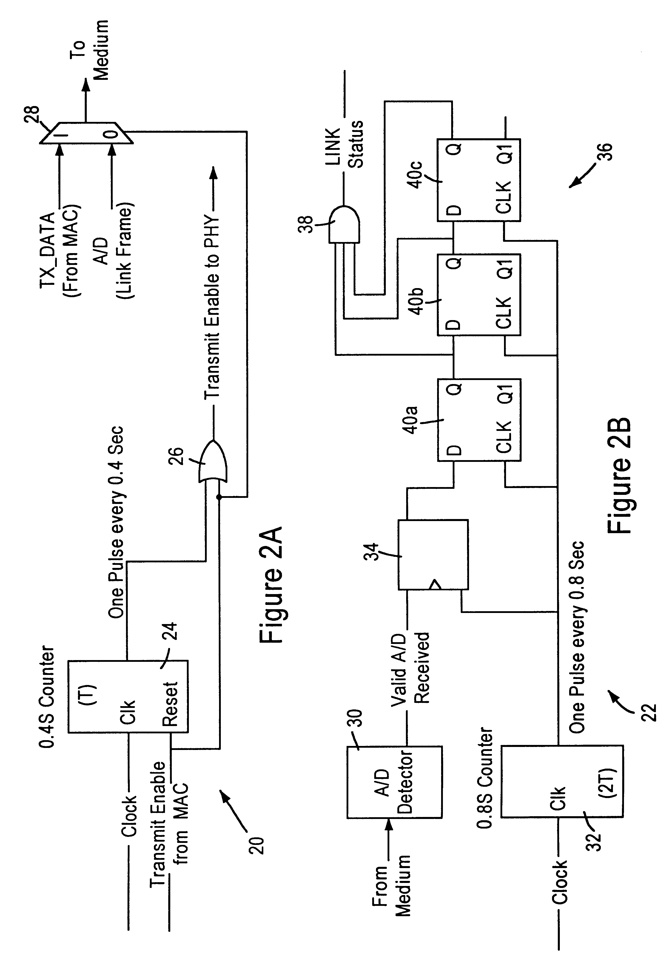
A local area network having a telephone line medium in a home network environment includes physical layer transceivers having transmit and receive state machines enabling each network station to determine a link status on the telephone line medium. The transmit state machine is configured for transmitting a link packet within a prescribed interval (T), less than a minimum packet length of a data packet, and having a preamble and a sufficient number of bytes to allow for transmission. Hence, the link packet will be detected by the other stations on the network, but will not be processed, since it is classified as a runt packet by the media access control layers. The receive state machine monitors the telephone line medium, and if after a prescribed interval (2T) the station has not detected a valid preamble from a data packet or a link packet, then the link status indicator for that station is set to an invalid condition, and subsequently supplied to the station operating system.

Description

1. Field of the InventionThe present invention relates to network interfacing, and more particularly, to methods and systems for detecting a link status between network stations connected to a telephone line medium.2. Description of the Related ArtLocal area networks use a network, cable or other media to link stations on the network. Each local area network architecture uses a media access control (MAC) enabling network interface cards at each station to share access to the media.Conventional local area network architectures use media access controllers operating according to half-duplex or full-duplex Ethernet (ANSI / IEEE standard 802.3) protocol using a prescribed network medium, such as 10 BASE-T. Newer operating systems require that a network station be able to detect the presence of the network. In an Ethernet 10 BASE-T environment, the network is detected by the transmission of a link pulse by the physical layer (PHY) transceiver. The periodic link pulse on the 10 BASE-T media...

Claims


Application Information

Patent Timeline
IPC IPC(8): H04L12/46
CPCH04L12/4612
Inventor KELLER, PHILIP J.
Owner GLOBALFOUNDRIES INC
Learn More