Separation by magnetic particles

Inactive Publication Date: 2001-10-02
BIO MAGNETICS LTD ISRAELI
View PDF17 Cites 131 Cited by
  • Summary
  • Abstract
  • Description
  • Claims
  • Application Information

AI Technical Summary

Benefits of technology

The membrane sheet can be placed on a planar magnet or a matrix of many magnets present on a planar surface in order to immobilize the magnetic particles and then the sheet can be dissolved by a suitable solvent. For ex

Problems solved by technology

Prior art methods, do not disclose methods for separating several molecular species from a sample simultaneously.
The disadvantage of such equipment, and similar equipments, resides in the necessity for manual handling, which requires, for example, manual pipettes to apply the samples onto the membranes.
One of the most severe problems in both formats of sequencing by hybridization technique is the time consuming step of washing of the filters.
The major technical problem with the method is to obtain scorable hybridizations with most of the probes over most of the clones.
Accuracy of the hybridization data is also a problem and the error rate could be increased from 3% due to higher dot density and uneven hybridization on larger filters.
A major problem in the combinatorial chemical synthesis of biological molecules is the need for individual purification of each molecule produced which is labor and time consuming.
Such particles are capable of responding well to relatively weak magnetic fields, but have essentially no magnetic memory, that is once the magnetic field is removed they do not maintain magnetic attraction forces.
(1) The biological entities separated from a sample solution in accordance with the invention can be easily recovered by collecting the magnetic particles and optionally dissociating the entities therefrom. The dissociation can be performed by transferring the magnetic particles into small volumes of suitable solutions with a very small loss of the biological entities, or alternatively by arranging those magnetic particles which bind the biological entities from the previous matrix to form a new matrix, for example, for sequencing by hybridization purposes.
(2) Where the separation of the entities is performed as part of an analysis, only entities of interest remain attached to the matrix of magnetic particles which is then further analy

Method used


Image

  • Separation by magnetic particles
  • Separation by magnetic particles
  • Separation by magnetic particles

Examples


example i

A. Construction of the magnetic matrix

Eight flat square fine tincoated magnets, 20 mm each side and 4 mm thick (VACODYM198 370 HR P / N 66750490, Vacuumschmelze GmbH, Germany) were attached in pairs to give 4 (40 mm.times.20) mm rectangles. Each of the 4 rectangles were separated from each other by 40 mm.times.20 mm.times.2 mm rubber sheets, to form alternating layers of magnets and rubber. This construction forms a box which narrow side has 4 strips of magnets 40 mm long and 4 mm wide, separated by strips of rubber 40 mm long and 2 mm thick and will be referred to hereinafter as the "stripped magnet ", or a flat magnet.

The above box can also be constructed without use of the rubber strips so its side has a dimension of 40.times.16 mm or 20.times.32 mm, which construct will be referred to hereinafter as the "uniform magnet".

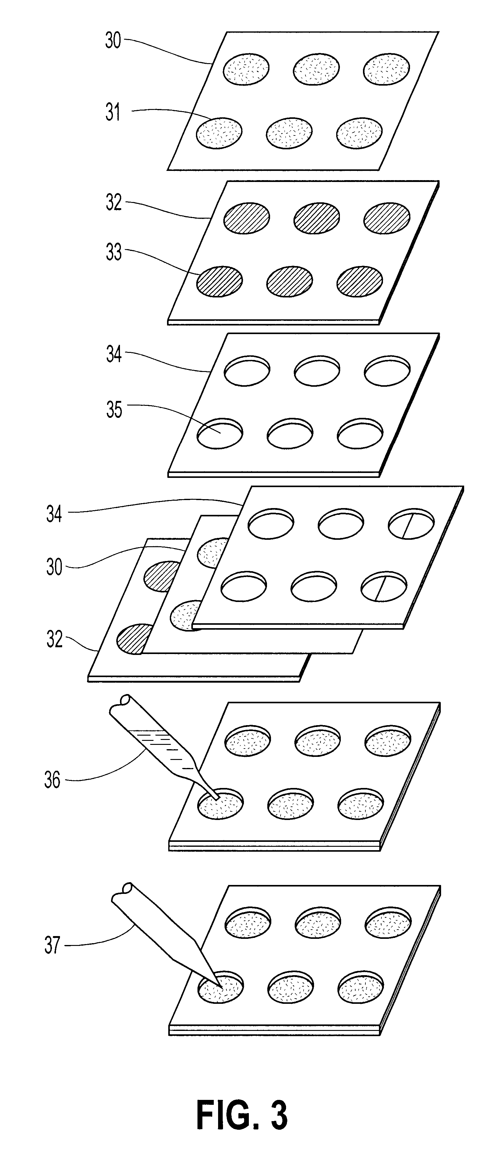
B. Preparing a magnetic particle matrix integrated in agarose

A silicon rubber rectangular frame 1 mm thick, 7.times.7 cm outer dimension and 5.times.5 cm inner cas...

example ii

Preparation of a matrix of magnetic particles as an integral part of the gel

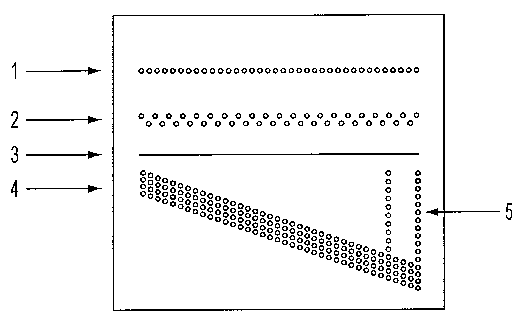
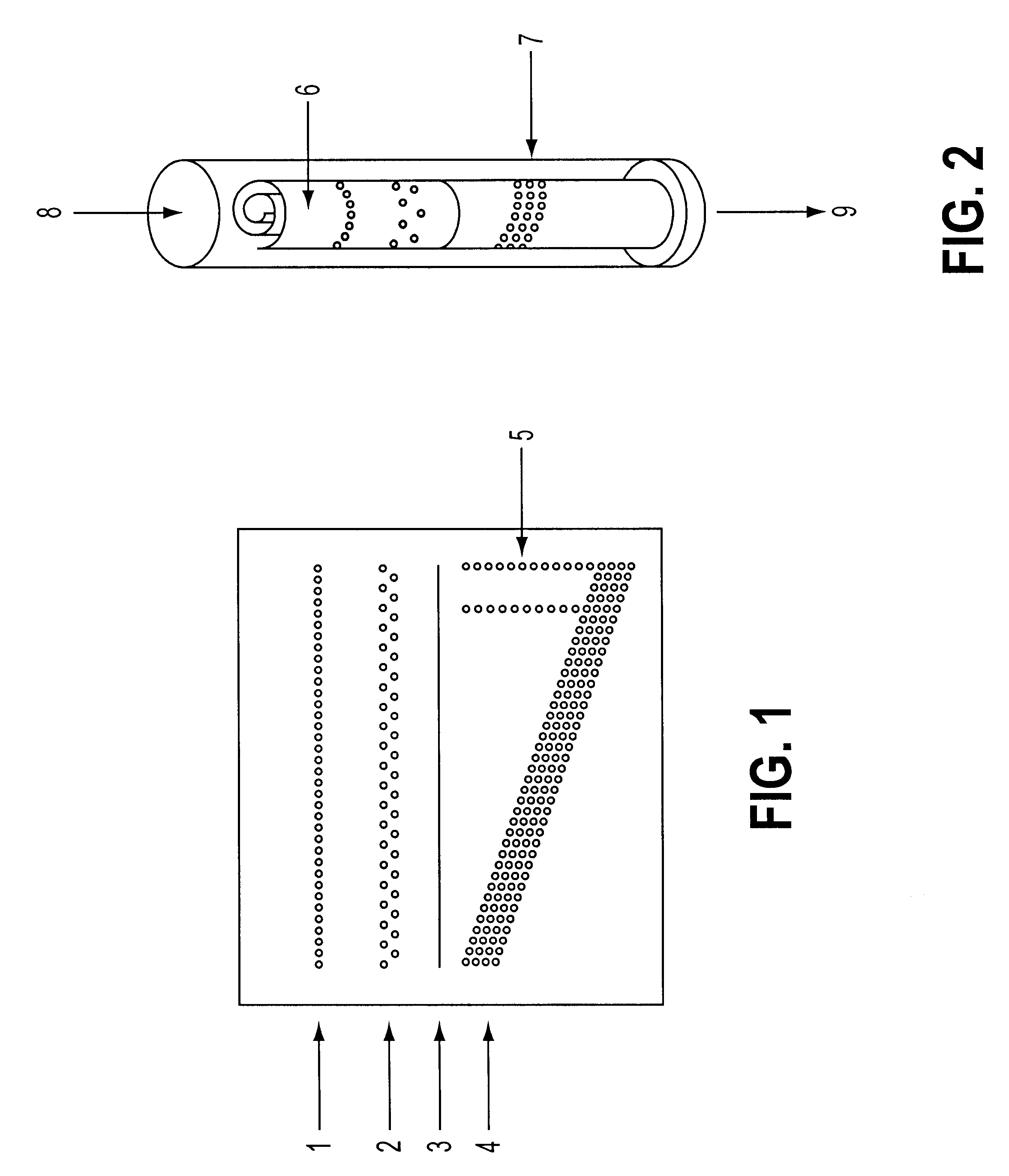
A solution of magnetic particles (EMG 705 Water Base Ferrofluid Ltd., Israel) was manually applied on to the surface of pergameneous paper with the aid of the tip of a glass Pasteur pipette in a pattern of diagonal strips, and left to dry for 1 hr.

The paper was then glued to a glass plate via contact glue or a double face adhesive tape. A silicon rubber rectangular frame, 1 mm thick, 7.times.7 cm outer dimension and 5.times.5 cm inner casting space was placed on the glued paper and attached by 4 clips. The glass plate was placed on a gel casting table equilibrated to a temperature of 35.degree. C. A polypropylene support net, 100 .mu.m thick, 200 .mu.m pore diameter was placed into the casting space prior to pouring the gel. 3 ml of 2% aqueous solution of agarose low-electroendosmosis (05071, Fluka, Switzerland) in a temperature of 60.degree. C. was poured into the casting space. The gel was covered with a g...

example iii

Collecting of magnetic particles from a specific location in a matrix

Four magnets as described above were placed on a 7.times.7.times.0.3 cm tin-coated iron plate in two pairs and separated from one another by a gap of 3 cm. The tin-coated iron plate was placed on the magnets and a tin-coated iron net having holes in the size of 1 mm was placed on the iron plate and held by the magnetic force of the two pairs of magnets. 1 gr iron powder, 50-150 .mu.m in particle size, was placed on the net and gently spread in the net area above the 3 cm gap between the magnets. The net and magnetic force held the particles so tightly that a wet filter paper placed on the net and pressed by a second tin-coated iron plate for 10 min. did not remove any of the particles.

A tapered electromagnet was used to collect the particles from the net. The net enables the collection of particles from each hole of 1 mm in size separately, with no lateral movement of particles from the other holes (see FIG. 5(a) a...


PUM

PropertyMeasurementUnit
Densityaaaaaaaaaa
Magnetismaaaaaaaaaa

Abstract

The present invention concerns a method for separating at least one species of biological entities from a sample solution, by contacting the sample with a matrix of magnetic particles formed on a substrate such as a sheet a gel, etc. The particles in the matrix are coupled to entities capable of specifically binding to the species of biological entities to be separated. The separation is carried out either for detection purposes for obtaining separately each species of biological entities or for synthesis purposes. The invention further concerns matrices of magnetic particles formed on various substrates and kits for use in the method.

Description

The present invention concerns a method for separating and detecting biological molecules, utilizing magnetic particles. The present invention fur tier concerns products, and kits used in said method, as well as methods for the preparations of said products.Magnetic particles are used for a variety of separation, purification, and isolation techniques in connection with biological biomolecules. In those techniques, a magnetic particle is coupled to a molecule capable of forming a specific binding (hereinafter "affinity binding") with a molecule in a biological sample, which is to be isolated, purified or separated. The biological sample is then brought into contact with the magnetic particle and those biological molecules which bind to the magnetic particle are then isolated by application of a magnetic field.Such magnetic separation techniques have been employed to sort cells, to recover antibodies or enzymes from a solution, to purify proteins using affinity techniques, and to rem...

Claims


Application Information

Patent Timeline
IPC IPC(8): G01N33/543
CPCG01N33/54326Y10S435/975Y10S436/824Y10S436/807Y10S436/808Y10S435/973Y10S436/809Y10S436/81
Inventor GOMBINSKI, MOSHE
Owner BIO MAGNETICS LTD ISRAELI
Why Eureka
Try Eureka