
Orthopedic implant system

a technology of implant system and orthopedic head, which is applied in the direction of prosthesis, femoral head, joint implant, etc., can solve the problems of excessive tissue response, patient discomfort and pain, and loose (or unstable) implant function, and achieve strong interlocking fixation

Inactive Publication Date: 2001-11-06
OSHIDA YOSHIKI
View PDF5 Cites 218 Cited by
  • Summary
  • Abstract
  • Description
  • Claims
  • Application Information

AI Technical Summary

Benefits of technology

It is, therefore, an object of the present invention to provide an orthopedic implant system which meets all three compatibilities (namely, biological, mechanical, and morphological), so that a strong interlocking fixation due to the bony ingrowth can be achieved.
It is another object of the present invention to provide the modified and reinforced polymethyl methacrylate resin as a bone cement as well as a material which can be used as a provisional crowns and bridges in dentistry, having a less temperature rise and shrinkage during the polymerization process.

Problems solved by technology

A loose (or unstable) implant may function less efficiently or cease functioning completely or it may induce an excessive tissue response.
In either case it may cause t he patient discomfort and pain and in several situations a loose implant is deemed to have failed and has to be surgically removed.
However, as one might expect, the situation is not quite this simple and loosening can occur, even with very accurate bone-bed preparation.
If the strain field in a metallic implant and bone system is not continuous, then the interface is not adhered and is easily debonded.
However, even the strain field is continuous, the stress field has always a discontinuity due to the differences in MOE values between two dissimilar materials.
If the discontinuous stress at an interface exceeds the interfacial bonding strength, then the bonding is failed.
If the pore size is smaller than 10 .mu.m, the surfaces will be more toxic to fibroblastic cells and has an adverse effect on cells due to their physical presence independent of any chemical toxic effects.
If the pore size is larger than 500 .mu.m, the surface does not exhibit any sufficient structural integrity.
However, the opening space is not morphologically compatible to surrounding bone, particularly the cancellous bone.
Any one of the beads (either made of Ti, hydroxyapatite, or PMMA) does not create sufficient opening space for the bony ingrowth and, then, is not morphologically compatible.
Even with the aforementioned efforts, there are several important factors unsolved.
These include (1) the heat generated during the polymerization of methyl methacrylate monomer, (2) the polymerization shrinkage, and (3) insufficient break strength and the modulus of elasticity.
Depending on the polymer formation rate, the temperature rise is reported in a range of 70 to 120.degree. C., which may irritate the surrounding hard and soft tissue and cause unexpected damage on them.
This amount of shrinkage is still too large and causes a dimensional accuracy and stability.

Method used


Image

  • Orthopedic implant system
  • Orthopedic implant system
  • Orthopedic implant system

Examples


embodiment

A production trial was carried out to fabricate a titanium foam metal sheet. For the present trial, a commercially available aluminum foam block which has an average open-cell size of about 1 mm diameter was employed. This block is a product from ERG, Inc., as described previously. A basic idea was to replicate the aluminum foam structure to be replaced by titanium metal. A molding cement was prepared and fed into open cells of the aluminum foam structure. After hardening the molding cement, the mold was heated in a furnace at 670.degree. C. for about 1 hour to let all aluminum melt and flow out the mold. Then the mold with open-cells was placed into a vacuum-controlled casting machine for titanium. After the all titanium was solidified, the mold was removed from the casting machine and the molding cement was removed by using the air-borne particle blasting machine with fine particle of aluminum oxide. The surface topology of titanium foam sheet was observed to be identical to origi...


PUM

PropertyMeasurementUnit
thicknessaaaaaaaaaa
thicknessaaaaaaaaaa
ultimate tensile strengthaaaaaaaaaa

Abstract

It is an object of the present invention to provide an improved orthopedic implant system with satisfied biological, mechanical and morphological compatibilities.Solid metal femoral stem and solid metal acetabular head are covered with diffusion-bonded foamed-shaped sheet made of commercially pure titanium or titanium alloy(s). The open-cells in said foamed metal sheet are impregnated with biocompatible polymethyl methacrylate resin cement, which is reinforced with selected oxides including alumina, magnesia, zirconia, or a combination of these oxides along with an application of a small amount of a metal primer agent.

Description

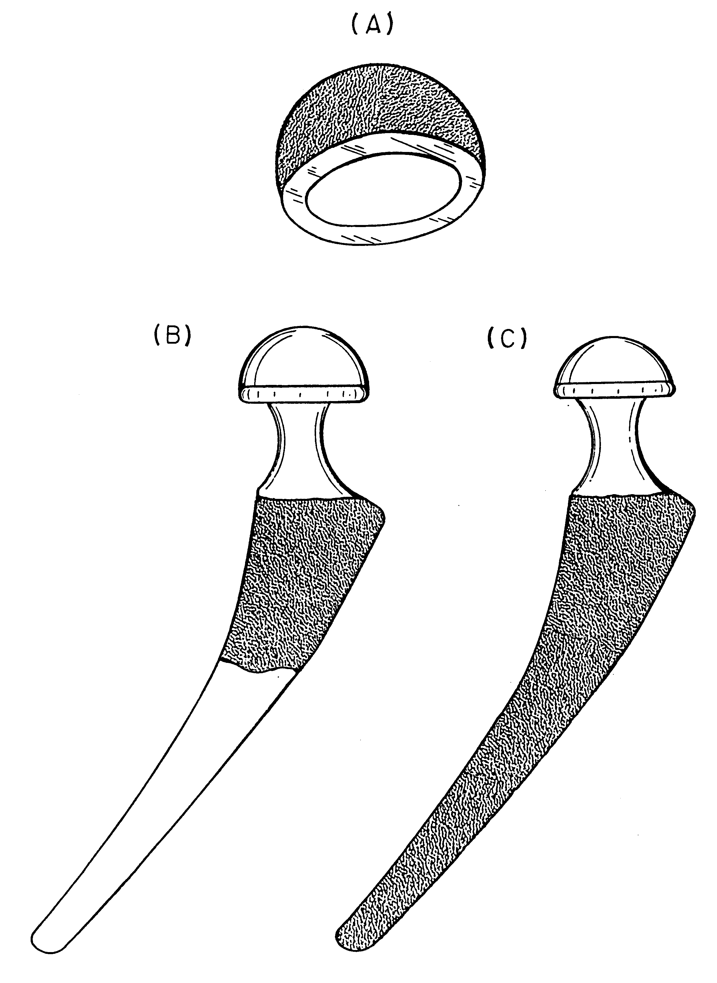
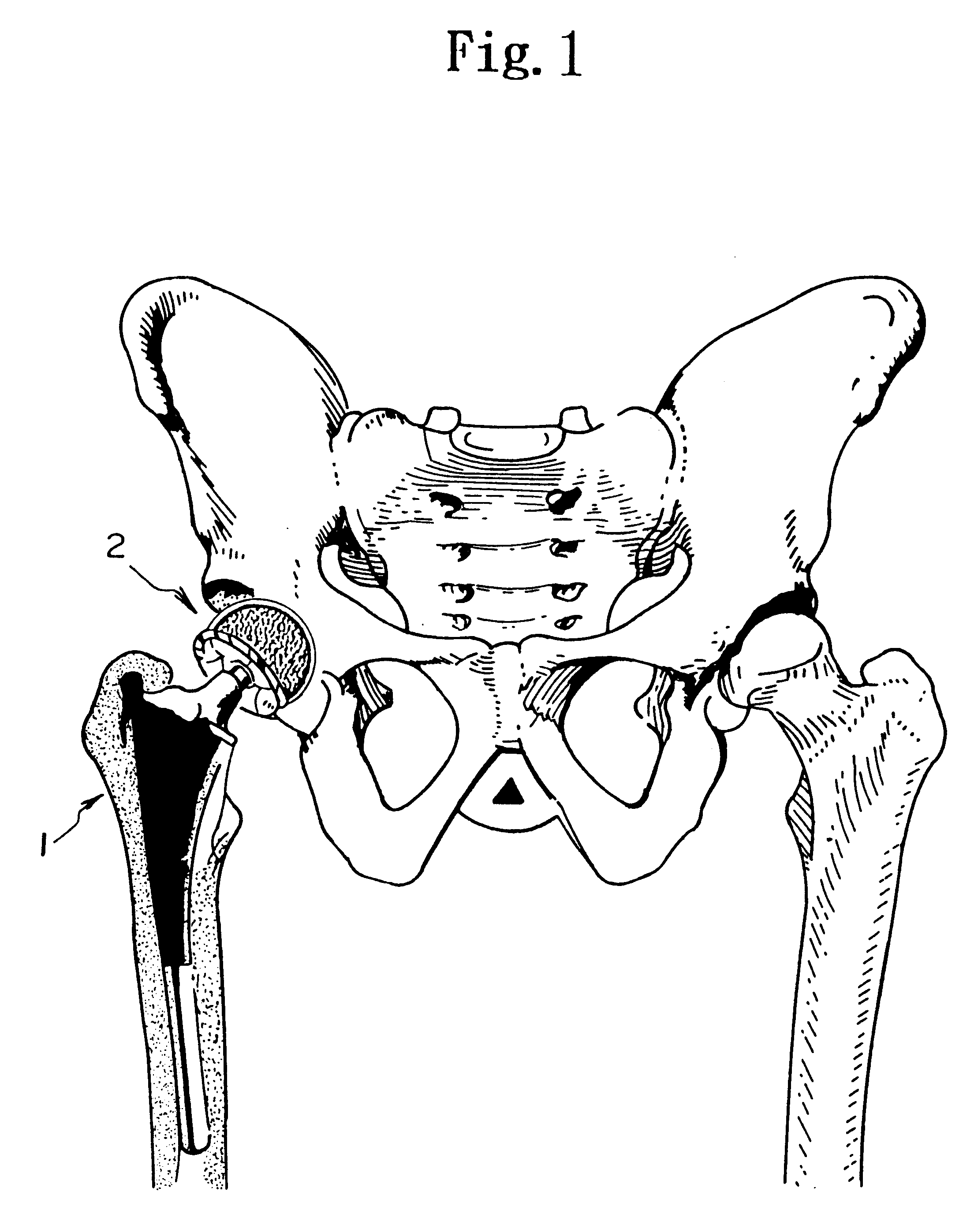
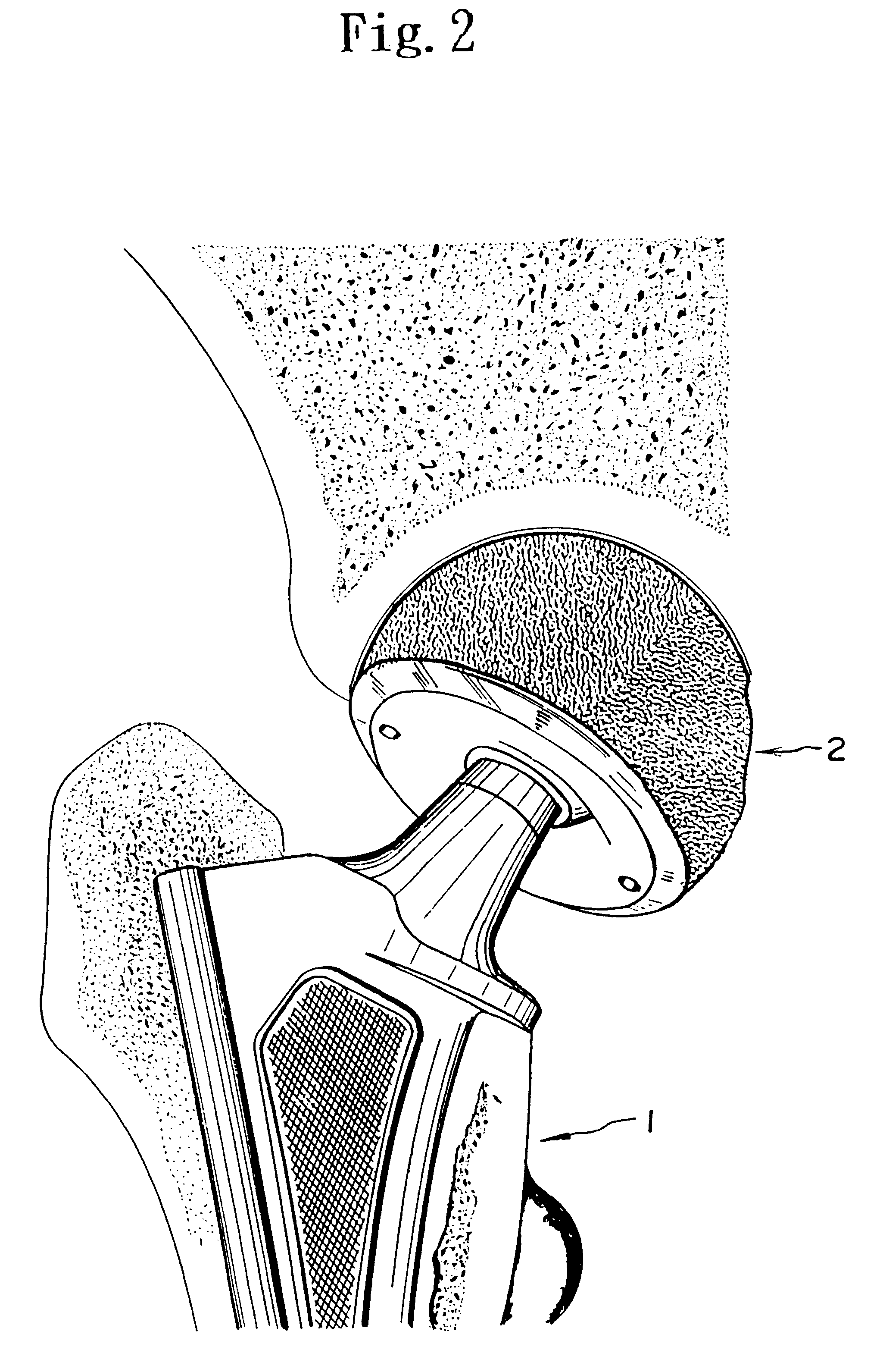
The present invention relates to an orthopedic implant system. More specifically, the present invention relates directly to a surface modification of the total hip prothesis system to improve the bony ingrowth for a better biological fixation, and to modify the bone cement in terms of both mechanical and physical properties.Total hip replacement prostheses have now been in use clinically for over 35 years. Most experience has been gained in the hip joint, where naturally, the prothesis is of the ball-head of the femoral stem and socket-type cup of the acetabular component. More recently reconstruction of the knee, elbow, shoulder and ankle have been attempted using prostheses of more varied mechanisms and design, although the basic concept for designing these prostheses remains unchanged.One of the many universal requirements of implants, wherever they are used in the body, is the ability to form a suitably stable mechanical unit with the neighboring tissues. A loose (or unstable) i...

Claims


Application Information

Patent Timeline
Patent Type & Authority Patents(United States)
IPC IPC(8): A61F2/30A61L24/00A61F2/32A61F2/00A61F2/36A61F2/34A61L27/00C22C19/07
CPCA61F2/30907A61L24/0089C08L33/12A61F2/32A61F2/34A61F2/36A61F2/367A61F2002/30451A61F2002/30454A61F2002/3092A61F2002/30957A61F2002/30967A61F2002/3611A61F2002/3631A61F2220/0058A61F2310/00407A61F2310/00952A61L2430/02
Inventor OSHIDA, YOSHIKI
Owner OSHIDA YOSHIKI
Learn More