Microwave and far infrared heating under reduced pressure

a technology of far infrared radiation and microwave heating, which is applied in microwave heating, electrical equipment, electric/magnetic/electromagnetic heating, etc., can solve the problems of difficult control of this type of heater, high production efficiency cannot be achieved, and the heaters of the prior art have a rotatable jig for rotating objects to be heated

Inactive Publication Date: 2001-11-27
YAGI SHUNICHI
View PDF10 Cites 18 Cited by
  • Summary
  • Abstract
  • Description
  • Claims
  • Application Information

AI Technical Summary

Problems solved by technology

However, prior art heaters having a rotatable jig for rotating objects to be heated are expensive and not suited for mass production due to the limited amount of objects that can be supported by the rotatable jig.
Further, the scattering of powder and relatively light particles occurs in prior art heaters which stir objects to be dried, and because such heaters are complex and expensive, they are not preferred.
Further, prior art heaters which move objects on a conveyor are quite suited for continuous production, but control of this type of heater is difficult.
Namely, because objects are continuously supplied, a mixture of objects having different water contents is created, and because this makes it difficult to accurately detect the completion of heating, a high production efficiency can not be achieved.
Further, because the accuracy in detecting the completion of heating is lowered, a control data base is required for each object when objects having different water contents are supplied at the time of each production, and this makes the control process extremely complicated.
Furthermore, such heating apparatuses are large in scale, and this together with the lower level of accuracy requires much time and cost to obtain conforming articles.
For the reasons given above, the use of heaters utilizing microwave and far infrared radiation under reduced pressure has not been widespread.
At this point, it should be mentioned that up to now it has been difficult to obtain uniform microwave heating and far infrared heating when the objects are not moved such as by rotation or agitation.
Further, prior art apparatuses and methods that continuously supply objects by moving them on top of a belt conveyor are suited for continuous production, but such arrangement makes it difficult to sufficiently control heating.
Namely, for continuous production to work with such prior art arrangement, the objects must be supplied and removed in order, and because this normally causes the immediately supplied objects having a high water content to mix with the objects that are near the completion of heating and have a low water content, the balance between th...

Method used


Image

  • Microwave and far infrared heating under reduced pressure
  • Microwave and far infrared heating under reduced pressure
  • Microwave and far infrared heating under reduced pressure

Examples


example embodiment 2

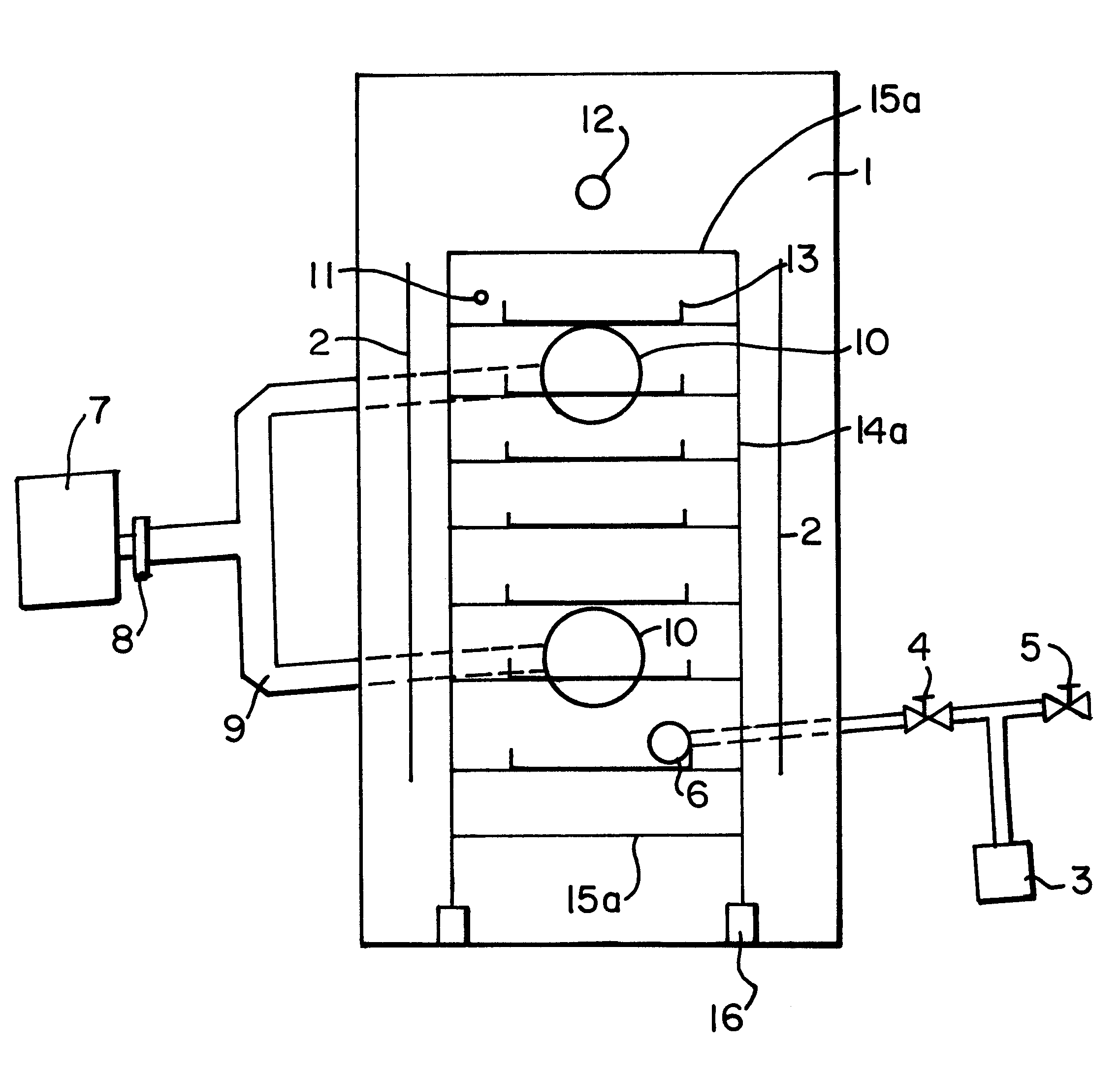
Next, using the structure described in Example Embodiment 1 a test of the effectiveness of a structure built in accordance with the embodiment described in claim 8 was carried out by drying 7 kg of seasoning paste. First, using a flat bottom tray, the paste was filled to a horizontal level, and then drying was carried out. When the tray was being removed, it was discovered that the center portion was not completely dried, so a drying process was carried out again. After the second drying, the center portion was completely dried, but a portion of the surrounding area was burnt. Next, a dome-shaped center bulging portion; convex portion 18 formed in the tray bottom having a diameter of 80 mm and a height of 7 mm was formed in the center of a tray or plate 13 to create a structure and then after this tray was filled with 7 kg of seasoning paste to a horizontal level, a drying process was carried out. In this case, a complete uniform drying of the paste was confirmed. In this connection...

example embodiment 3

Next, a test of the effectiveness of a structure where the object holding jigs are open shaped and are made of heat resistant and microwavable material was carried out by concentrating 7 kg of strawberries. First, the strawberries were loaded onto aluminum plates, and then drying was begun with a goal of removing 60% of the water content. However, because microwave radiation can not penetrate through the bottom surface of the aluminum plates, only 35% of the water content was removed within a prescribed drying time. Next, 7 kg of strawberries were loaded onto plates made of polysulfone, and after drying was carried out for the prescribed drying time, it was confirmed that roughly 60% of the water content had been removed. Further, when these dried strawberries were ground up, an extremely delicious paste was created.

example embodiment 4

Next, a concentration process for concentrating 7 kg of strawberries was carried out again for the case of a plate where the object-holding jigs are made from paper and the portions that come into contact with the objects are coated with a microwave permeable resin or covered with paper coated with a microwave permeable resin. Namely, after a 1 mm-thick cardboard plate was prepared and covered with a sheet of silicon-treated paper, the strawberries were loaded and drying was begun. After drying had been carried out over the prescribed drying time, measurements were taken, and the results showed that 55% of the water content had been removed. Further, even though a small quantity of the strawberries had rolled away, the provision of the sheet made it possible to smoothly pick up all the concentrated strawberries.


PUM


Abstract

Microwave and far infrared heating under reduced pressure is carried out on objects to be dried, concentrated, defrosted, roasted or sterilized by placing the objects in plate-shaped or tray-shaped object-holding jigs arranged on a shelf-type jig which is held motionless in a pressure reducing chamber during heating, wherein the provision of reflector plates, reflective frames, specific object-holding jigs and cutting methods are employed to achieve uniform heating.

Description

1. Field of the InventionThe present invention relates to a method and apparatus for heating objects using microwave and far infrared radiation under reduced pressure for the purpose of drying, concentrating, defrosting, roasting or sterilizing the objects.2. Description of the Prior ArtIn prior art heaters which utilize microwave and far infrared radiation for drying, concentrating, defrosting, roasting or sterilizing objects, uniform heating is achieved by placing the objects in a chamber on jigs such as plates or trays and shelf-type support jig for supporting the jigs which is rotated or on a conveyor which is moved, or the objects are stirred.However, prior art heaters having a rotatable jig for rotating objects to be heated are expensive and not suited for mass production due to the limited amount of objects that can be supported by the rotatable jig. Further, the scattering of powder and relatively light particles occurs in prior art heaters which stir objects to be dried, an...

Claims


Application Information

Patent Timeline
IPC IPC(8): H05B6/80H05B6/64
CPCH05B6/6408H05B6/6482
Inventor YAGI, SHUNICHI
Owner YAGI SHUNICHI
Why Eureka
Try Eureka