Increased ion beam throughput with reduced beam divergence in a dipole magnet

a dipole magnet and ion beam technology, applied in the direction of discharge tube/lamp details, magnetic discharge control, instruments, etc., can solve the problems of high reliability, high cost, and limited consistency and manufacturing yield, and achieve high reliability and reliability. , the ability to determine the electrical properties of high precision, and the difficulty of reducing the number of ion beams

Inactive Publication Date: 2001-11-27
IBM CORP +1
View PDF1 Cites 7 Cited by
  • Summary
  • Abstract
  • Description
  • Claims
  • Application Information

AI Technical Summary

Problems solved by technology

The capability to determine the electrical properties with high reliability, consistency and manufacturing yield is often limited, as a practical matter, by the tools used for processing the semiconductor material, usually in the form of a wafer.
Such tools are often complex and of high precision.
Therefore such tools are generally expensive to build and maintain.
The principal expense of modern semiconductor devices is thus a portion of the cost of the tools used to produce them and, therefore, varies inversely with tool throughput.
Accordingly, the desired concentrations of impurities may r

Method used


Image

  • Increased ion beam throughput with reduced beam divergence in a dipole magnet
  • Increased ion beam throughput with reduced beam divergence in a dipole magnet
  • Increased ion beam throughput with reduced beam divergence in a dipole magnet

Examples


Embodiment Construction

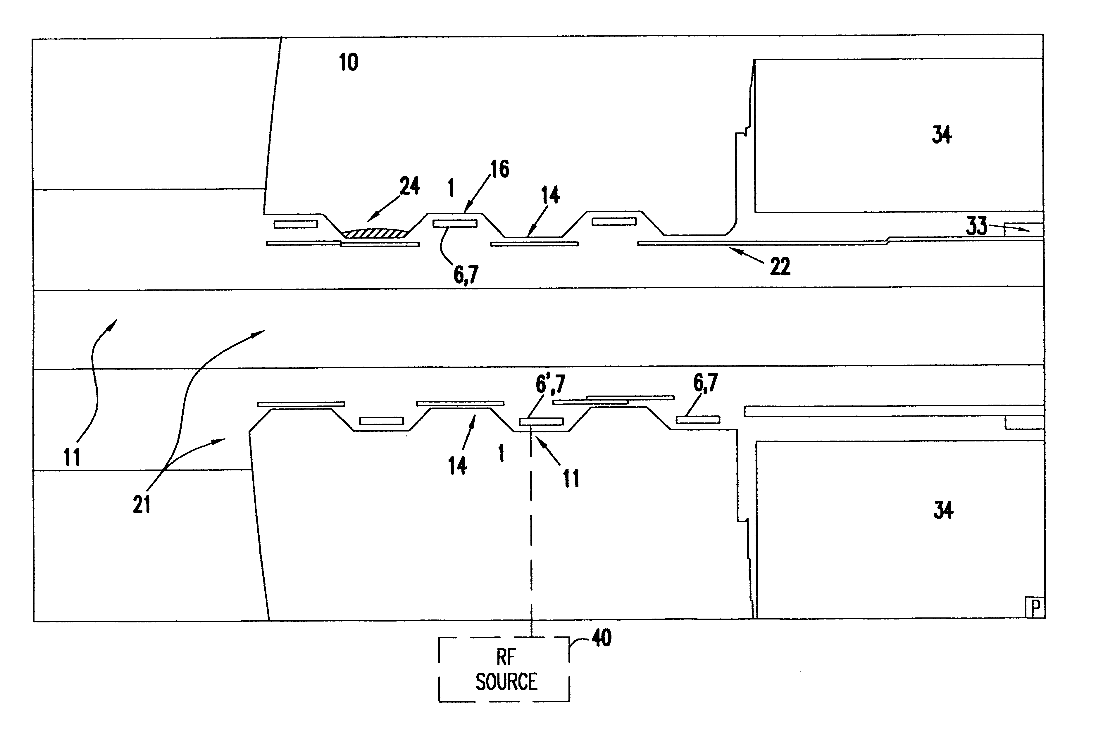
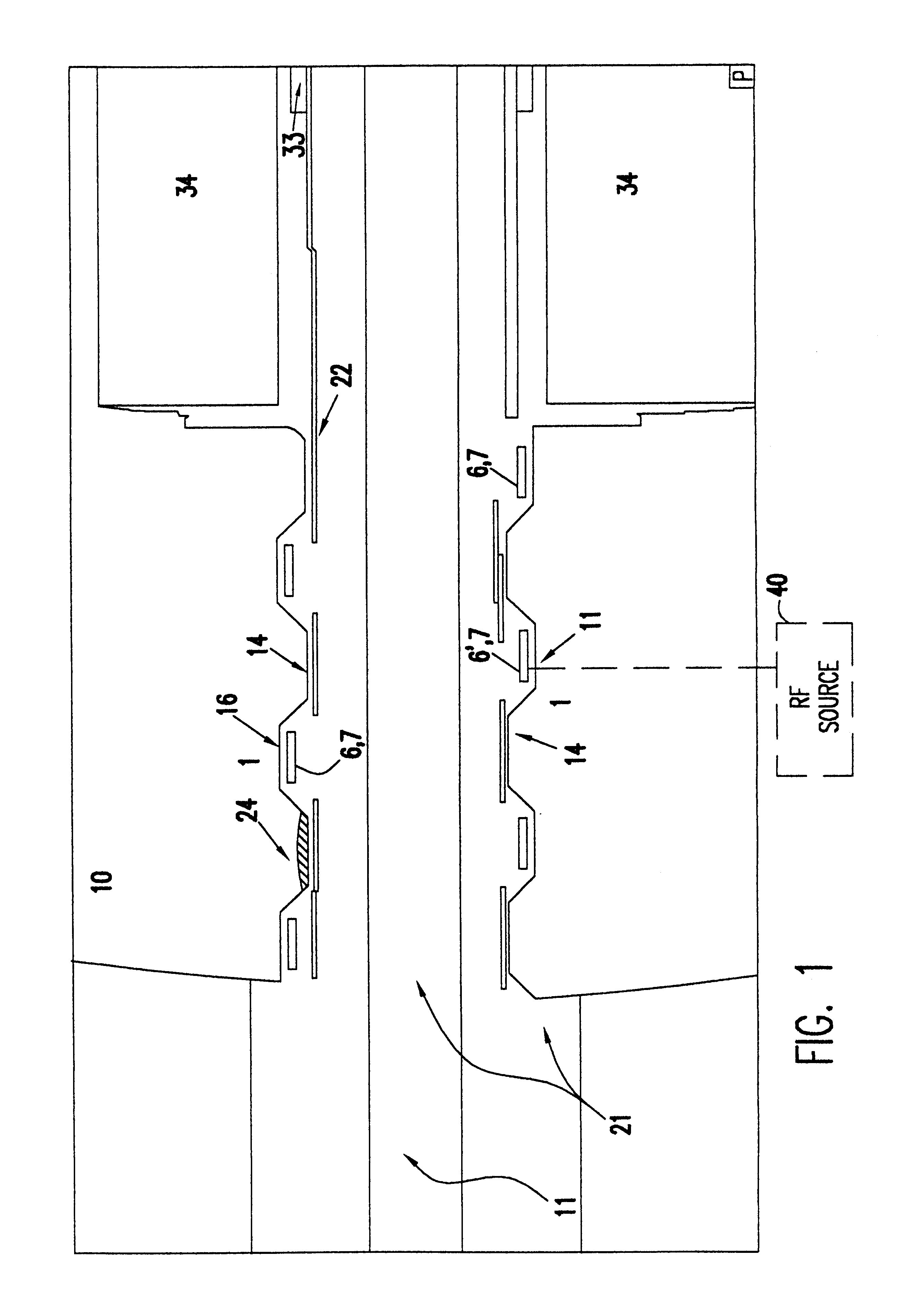
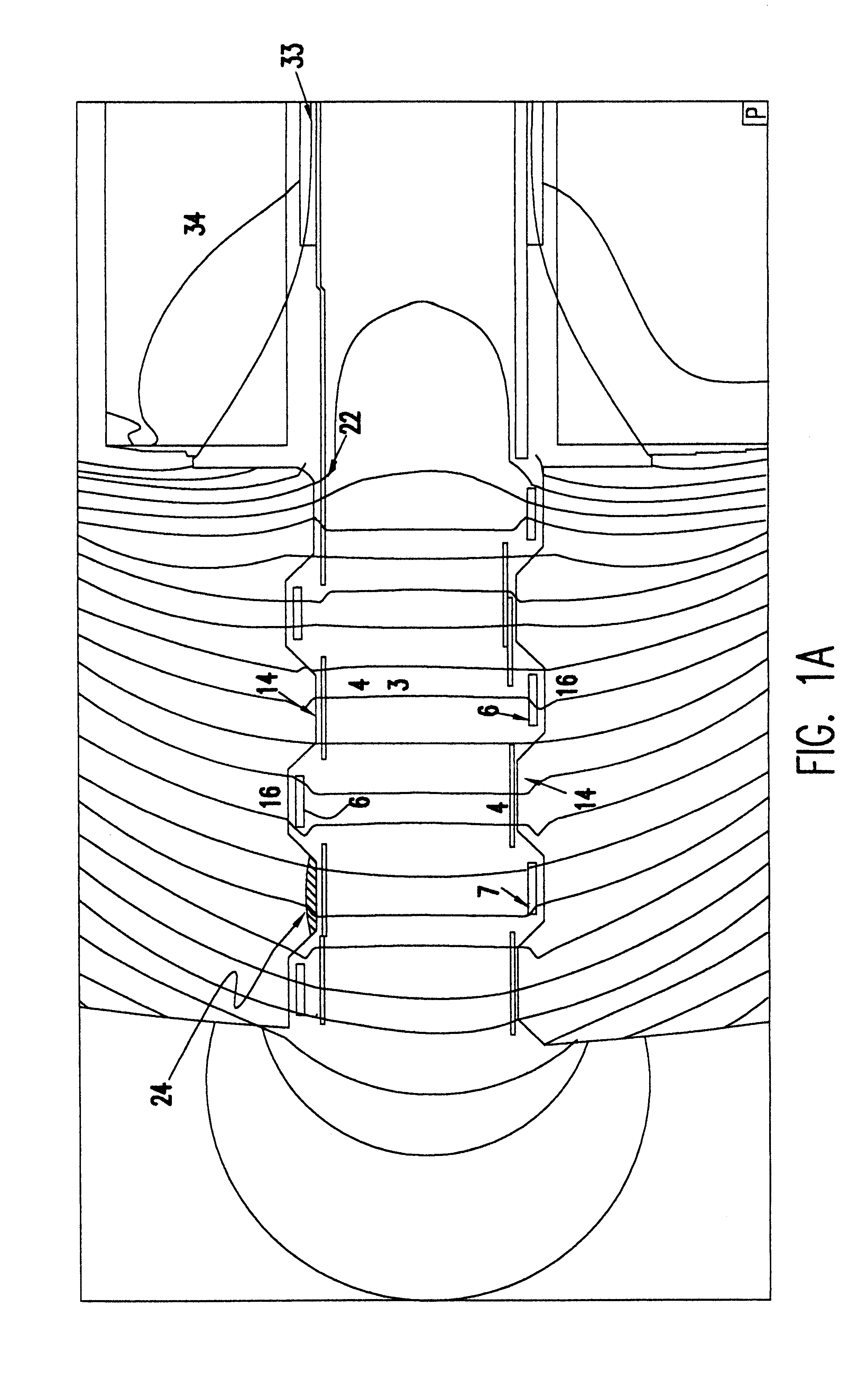
Referring now to the drawings, and more particularly to FIGS. 1 and 1A, there is shown, in cross section, the gap of a dipole magnet such as may be used for mass analysis or any other manipulation of the ion beam in accordance with one exemplary embodiment of the invention. The magnetic field pattern is depicted in FIG. 1A to aid in visualization of the principles of the invention but omitted from FIG. 1 in the interest of clarity.

It should be understood that in an ion beam transport system in which the beam is travelling near the local ground potential or where there are no electrodes to draw off electrons, the ion beam will produce a beam plasma by ionization of the background neutral gas. The number of ions and electrons produced to form the plasma will depend on the pressure of the background gas and the beam energy. In general, the beam plasma will partially fill the beam line or beam raceway which is provided to surround the beam. It will thus be in the region of the beam and ...


PUM


Abstract

Spreading of an ion beam when passing through a dipole magnet is reduced or suppressed by electrostatic ion beam confinement which supplements magnetic confinement which may be provided. The magnetic confinement is enhanced by the provision of a magnetic mirror through concentration and localized increase of the dipole field with a concave profile of the pole pieces faces and/or provision of permanent magnets or localized regions of material of increased permeability to form magnetic cusps. Pitch and geometry of convex portions of the pole piece faces are adjusted to increase the mirror ratio and the location of the maximum mirror field relative to the thickness of a graphite or insulating liner which may be employed. Electrostatic confinement elements in the form of negatively charged electrodes and/or electrically isolated electrodes or insulators which assume a negative charge. Ionization of plasma between the pole pieces may be enhanced by application of a VHF/UHF field having a frequency of about 40 MHz to 100 MHZ or higher.

Description

1. Field of the InventionThe present invention generally relates to apparatus employing charged particle beams and, more particularly, to ion beam apparatus employing magnets to manipulate the ion beam.2. Description of the Prior ArtThe art of semiconductor electronic device manufacture has become highly sophisticated in recent years to provide a wide range of electrical properties of the devices, often at very high integration density. The capability to determine the electrical properties with high reliability, consistency and manufacturing yield is often limited, as a practical matter, by the tools used for processing the semiconductor material, usually in the form of a wafer. Such tools are often complex and of high precision. Therefore such tools are generally expensive to build and maintain. The principal expense of modern semiconductor devices is thus a portion of the cost of the tools used to produce them and, therefore, varies inversely with tool throughput.As is generally k...

Claims


Application Information

Patent Timeline
IPC IPC(8): H01J37/04
CPCH01J37/04H01J37/3266
Inventor KELLER, JOHN H.KELLER, KATHLEEN J.
Owner IBM CORP
Why Eureka
Try Eureka