
Lithium manganate, method of producing the same, and lithium cell produced by the method

a lithium cell and manganate technology, applied in the direction of lithium compounds, manganates/permanentates, cell components, etc., can solve the problems of low difficult to obtain uniform composition, and inability to control particle size, etc., to achieve excellent cycle characteristics and high initial charge and discharge capacity

Inactive Publication Date: 2002-01-01
ISHIHARA SANGYO KAISHA LTD
View PDF11 Cites 40 Cited by
  • Summary
  • Abstract
  • Description
  • Claims
  • Application Information

AI Technical Summary

Benefits of technology

Furthermore, that the initial discharge capacity is at least 95 mAh / g when the lithium manganate is used as an active material for positive electrodes of lithium batteries can be easily confirmed by conducting the measurement in the state of battery and under the measuring conditions mentioned hereinafter.
By employing the above construction, the lithium secondary batteries which contain the lithium manganate of the present invention as an active material of positive electrodes are high in initial charge and discharge capacity and excellent in cycle characteristics.

Problems solved by technology

Thus, there is a problem that size of particles cannot be controlled.
Moreover, since a mixture of a manganese compound and a lithium compound is inferior in reactivity even when it is fired at high temperatures, uniform composition can hardly be obtained and there are many lattice defects.
Furthermore, lithium secondary batteries which use lithium manganate obtained by the above process as an active material for positive electrodes are not only low in initial charge and discharge capacity, but also show conspicuous reduction in capacity with repetition of charge and discharge.
This is because crystals of lithium manganate are collapsed at the time of charging and discharging, which is considered to be caused by the presence of lattice defects and the low lithium ion conductivity.
For the solution of the above problems, there is proposed a process which comprises impregnating a porous manganese dioxide with lithium acetate, lithium nitrate or lithium hydroxide and obtaining a product of uniform composition at low temperatures (for example, "Electro-chemistry (Denki Kagaku)", 63, 941 (1995)), but this process is still not sufficient.

Method used


Image

  • Lithium manganate, method of producing the same, and lithium cell produced by the method
  • Lithium manganate, method of producing the same, and lithium cell produced by the method

Examples


example 1

(Synthesis of manganese hydroxide)

815 g of manganese sulfate (86% by weight as MnSO.sub.4) was dissolved in water to prepare 6.179 liters of a solution. This aqueous manganese sulfate solution was charged in a glass reaction vessel of 10 liters, and, with stirring, 2.321 liters of sodium hydroxide of 4 mols / l in concentration was added to and dispersed in the aqueous solution over a period of 1 hour in a nitrogen atmosphere with keeping the temperature at 15.+-.5.degree. C. to obtain a manganese hydroxide.

(Synthesis of manganese oxide)

The resulting slurry containing manganese hydroxide was heated to 60.degree. C., and air was blown thereinto for 1 hour to oxidize the manganese hydroxide in an aqueous medium, followed by aging for 1 hour with blowing nitrogen gas in place of the air and thereafter filtering and washing with water. The resulting filter cake was dried at 110.degree. C. for 12 hours to carry out gas phase oxidation to obtain a manganese oxide. This manganese oxide was l...

example 2

(Synthesis of manganese hydroxide)

A manganese hydroxide was obtained in the same manner as in Example 1.

(Synthesis of manganese oxide)

A manganese oxide was obtained in the same manner as in Example 1.

(Synthesis of lithium manganate precursor)

The resulting manganese oxide (240 g in terms of Mn) was dispersed in water to prepare a slurry. Pure water and 0.870 liter of lithium hydroxide of 3.206 mols / l in concentration were added to the slurry to obtain 2.40 liters of a liquid. This was charged in a glass reaction vessel of 3 liters and heated to 80.degree. C., and reaction was carried out for 3 hours with blowing air thereinto. The evaporated water was replenished and then a part of the slurry was taken, and alkali concentration thereof was measured to find that 16.4% by weight of the added lithium reacted with the manganese oxide. The slurry was charged in an autoclave and subjected to hydrothermal treatment at 150.degree. C. for 2 hours. The slurry was cooled to 80.degree. C. and th...

example 3

(Synthesis of manganese hydroxide)

A manganese hydroxide was obtained in the same manner as in Example 1.

(Synthesis of mangane se oxide)

A manganese oxide was obtained in the same manner as in Example 1.

(Synthesis of lithium manganate precursor)

The resulting manganese oxide (186.5 g in terms of Mn) was dispersed in water to prepare a slurry. Pure water and 0.746 liter of lithium hydroxide of 3.000 mols / l in concentration were added to the slurry to obtain 2.40 liters of a liquid. This was charged in a glass reaction vessel of 3 liters and heated to 80.degree. C., and reaction was carried out for 3 hours with blowing air thereinto. The evaporated water was replenished and then a part of the slurry was taken, and alkali concentration thereof was measured to find that 13.8% by weight of the added lithium reacted with the manganese oxide. The slurry was charged in an autoclave and subjected to hydrothermal treatment at 180.degree. C. for 2 hours. The slurry was cooled to 80.degree. C. and...


PUM


Abstract

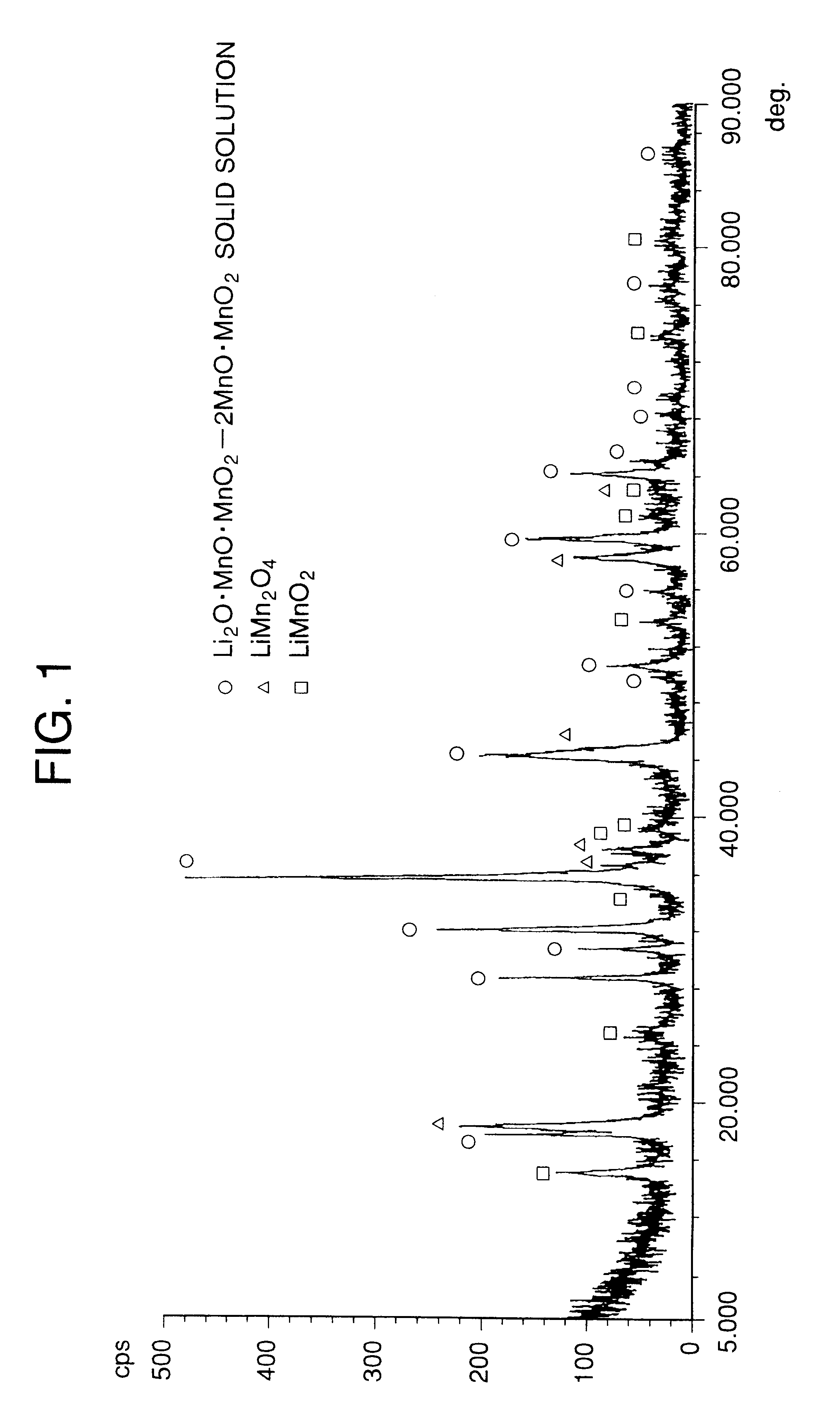
The present invention relates to a lithium manganate useful as an active material of positive electrodes for lithium batteries, and a process for producing the same, a positive electrode which uses the same as an active material of positive electrode, and a lithium battery. The lithium manganate of the present invention has a cubic particle form and contains voids in the particles, and therefore lithium batteries using it as an active material of positive electrodes provides a high initial discharge capacity of at least 95 mAh / g and, besides, are excellent in cycle characteristics.

Description

The present invention relates to lithium manganate which is a compound useful as an active material for positive electrode for lithium battery, a process for producing the same, a positive electrode for lithium battery using the same as an active material for positive electrode, and a lithium battery.Lithium manganate is a compound represented by the formula Li.sub.x Mn.sub.y O.sub.4, and representative are spinel type LiMn.sub.2 O.sub.4, Li.sub.4 / 3 Mn.sub.5 / 3 O.sub.4 and the like. For obtaining such lithium manganates, a process of firing a mixture of a manganese compound and a lithium compound at a temperature of about 800.degree. C. is employed.DISCLOSURE OF INVENTIONLithium manganate obtained by the above conventional process is apt to become a sintered body in which non-uniform sintering occurs between particles because a mixture of a manganese compound and a lithium compound is fired at about 800.degree. C. for the purpose of adjustment of valence of manganese or diminishment ...

Claims


Application Information

Patent Timeline
IPC IPC(8): C01G45/00H01M4/50C01G45/02H01M4/505C01G45/12H01M10/05
CPCC01G45/02C01G45/1221C01G45/1242H01M4/0471H01M4/505H01M10/052C01P2004/61C01P2004/62C01P2006/12Y02E60/122C01P2006/40H01M4/02H01M2004/021C01P2006/14Y02E60/10H01M4/04H01M10/0525
Inventor SUITA, TOKUOMIYAZAKI, HIROMITSU
Owner ISHIHARA SANGYO KAISHA LTD
Learn More