
Automotive-wire insulation

a technology for automobiles and wires, applied in the direction of insulated conductors, plastic/resin/waxes insulators, cables, etc., can solve the problems of oxidation of polyolefins, brittle insulation, and oxidation cracks on bending, and achieve excellent insulation. excellent, the effect of insulating properties

Inactive Publication Date: 2002-03-19
CHAMPLAIN CABLE CORP
View PDF20 Cites 84 Cited by
  • Summary
  • Abstract
  • Description
  • Claims
  • Application Information

AI Technical Summary

Benefits of technology

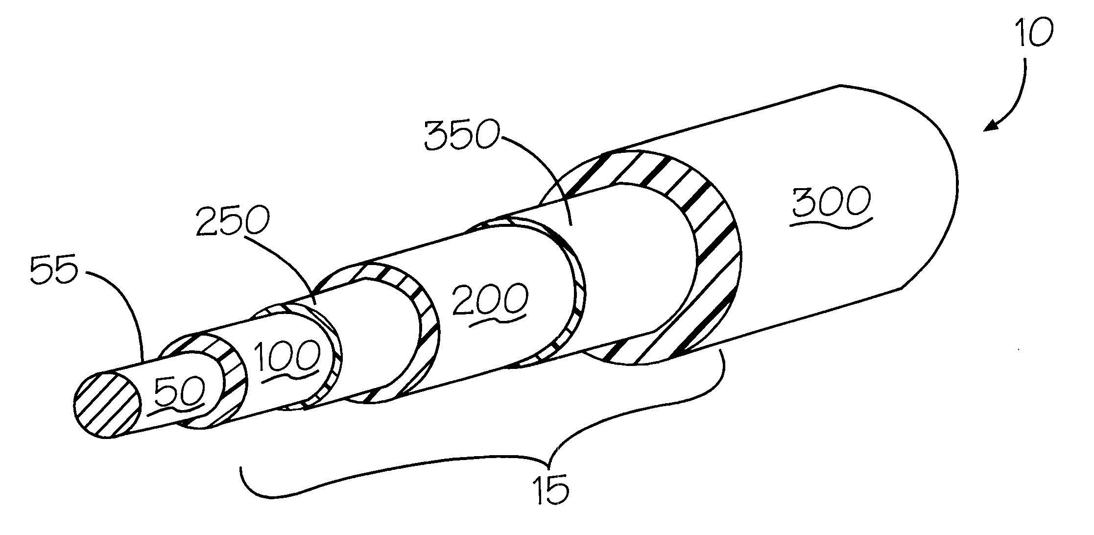
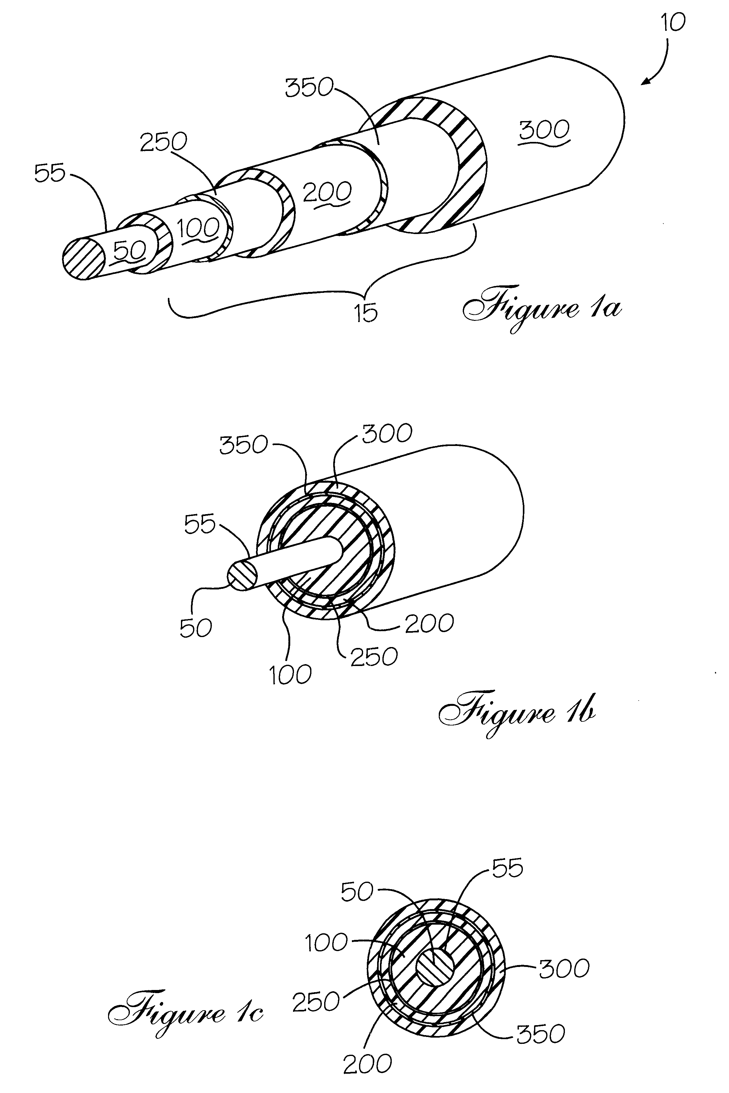
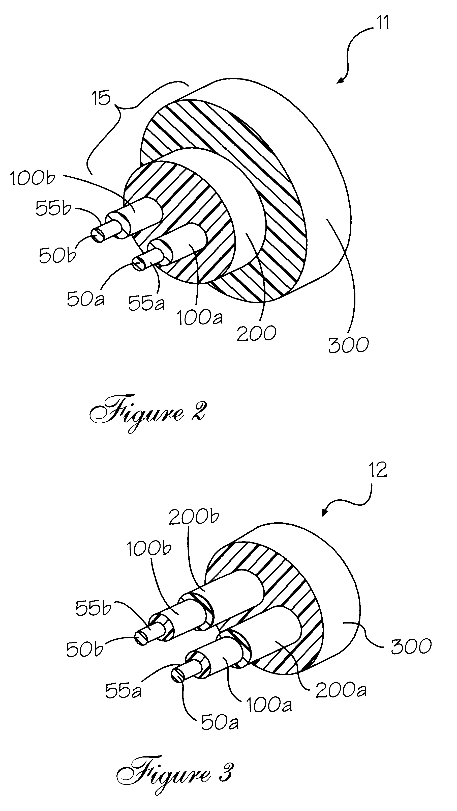
In accordance with the present invention, there is provided a high-temperature, automotive-wire article having a thin wall construction and an operative temperature that is greater than 135.degree. C. The wire article comprises an inner core of metal that is surrounded by a polymer insulation, the latter including an integral composite of three layers. The first, inner layer of the composite comprises a polymeric material that is insensitive to copper catalyzed degradation, while the second, intermediate layer of the composite comprises a polyolefin material that is preferably crosslinked by irradiation. Irradiation cross-linking requires a dose of approximately 60 to 400 kGy, and preferably between 100 and 200 kGy. The third, outer layer of the insulative tri-pack is a fluorinated polymer having excellent physical toughness and chemical inertness. It is specifically selected to limit the oxidation of the underlying polyolefin layer.

Problems solved by technology

If varnish is inadvertently applied to the polyolefin insulation, the insulation becomes brittle and cracks on bending.
However, no mention is made of the problem of oxidation of the polyolefin.
Wessels states that fluoro-containing polymers, while being excellent insulators, are expensive.
This is because their properties are adversely affected by irradiation.

Method used


Image

  • Automotive-wire insulation
  • Automotive-wire insulation
  • Automotive-wire insulation

Examples


example 2

n)

The wire as described in Example 1 is further coated with a third, outer insulative layer comprising a polymeric composition containing a co-polymer of ethylene and chlorotrifluoroethylene (ECTE) marketed by Ausimont USA Inc under the tradename HALAR.RTM.. This third layer has a 0.15 mm radial thickness. The critical test performed on Example 1 and 2 coated wires is described in ISO 6722-1 1996 sections 10.2 and 10.3.1 and is shown in Table I as "Days to 50% failure at 180.degree. C.".

To further illustrate the benefit of the current invention Examples 3 to 7 are provided where one or more of the insulative layers are removed. As will be noted there is a substantial increase in the "Days to 50% failure at 180.degree. C." when the entire inventive design comprising three insulative layers are employed compared to any of the comparative examples. This increase in lifetime is unexpected since no reported studies have been performed on the interaction of the degradative mechanisms of p...

example 3

on)

The wire article 10 comprises a conductive core 50 with a diameter of 0.95 mm bare copper that is surrounded by a composite insulation having insulative layer 200 extruded over the metal core. The insulative layer is 0.40 mm thick and comprises a cross-linked polyethylene (XLPE) that has been electron beam irradiated with approximately 150 kGy.

example 5 (

Invention)

The coated wire from Example 4 is further coated with a third, outer insulative layer of ethylene chlorotrifluoroethylene copolymer having a radial thickness of 0.075 mm.


PUM

PropertyMeasurementUnit
thickaaaaaaaaaa
operative temperatureaaaaaaaaaa
temperatureaaaaaaaaaa

Abstract

The invention pertains to multi-layer polymeric formulations for protecting or insulating metallic objects, and, more particularly, to an integrated, tri-layer, thin-wall insulation composite, for use in a high temperature, automotive-wire article. The tri-layer design comprises an inner layer of a fluoropolymer, polyether sulfone, polyether-ketone, polyetherimide, or thermoplastic polyester; a middle layer comprising a polyolefin; and an outer layer comprising a fluoropolymer. The inner and outer layers serve to protect the middle polyolefinic layer from degradation.

Description

The invention pertains to multi-layer polymeric formulations for protecting or insulating metallic objects and more particularly, to an integrated, tri-layer, thin-wall insulation composite, for use in a high temperature, automotive-wire article.Applying polymeric formulations to the surface of metallic objects has been a long practiced art. Typically, this is performed for several different reasons. Firstly, metallic objects are prone to oxidation or other chemical attack of their surfaces, degrading the utility of the metal object. Secondly, metals are inherently electrically conductive, metallic articles used for this purpose must be insulated to maintain the integrity of the electrical circuit. Examples of applications of such articles include such diverse uses as building wire, aircraft wire, plenum wiring for local area network computers and communication, transformer wiring for isolating magnetic and electrical wiring, underground wiring, and electrical conductive wiring for ...

Claims


Application Information

Patent Timeline
Patent Type & Authority Patents(United States)
IPC IPC(8): H01B3/44H01B7/17H01B7/29
CPCH01B7/292H01B3/441
Inventor HILDRETH, NELSON
Owner CHAMPLAIN CABLE CORP
Learn More