Photoreceptor with layered charge generation section

a photoreceptor and charge generation technology, applied in the field of photoreceptors, can solve the problems of inability to meet the needs of the user, and increase the cost of manufacturing photoreceptors, so as to achieve stable pigment dispersions, high-quality photoconductive coatings, and maximize sensitivity

Inactive Publication Date: 2002-04-23
XEROX CORP
View PDF24 Cites 51 Cited by
  • Summary
  • Abstract
  • Description
  • Claims
  • Application Information

AI Technical Summary

Benefits of technology

It is an object of the present invention to provide an improved photoreceptor having high quality photoconductive coatings which overcomes the above-noted deficiencies. It is another object of the invention to provide for stable pigment dispersions for use in photoreceptors. It is yet another object of the invention to maximize sensitivity in a fixed narrow wavelength band and in the near infra-red wavelength region. It is yet another object of the invention to maximize sensitivity over a broadband of exposure.

Problems solved by technology

However, these classes of pigments in many instances have low or negligible photosensitivity in the near infrared region of the spectrum, for example between about 750 and 970 nanometers, thereby preventing their selection for photoresponsive imaging members in electronic printers wherein electronic light emitting devices, such as GaAs diode lasers, are commonly used as a light source to create an electrostatic image on the imaging members.
Also, some of the above mentioned organic pigments have a narrow and restricted spectral response range such that they cannot reproduce certain colors present in the original documents, thus resulting in inferior copy quality.
The cost to develop different photoconductive pigments and different charge generation section coating dispersion formulations and to change dispersion solutions for different products in the manufacturing process greatly increases the costs to manufacture photoreceptors.
The net outcome of all these variables is that the electrical characteristics of photoreceptors may be inconsistent during the manufacturing process.
A common problem encountered in the manufacturing of photoreceptors is maintaining consistent spectral and broadband sensitivity from batch to batch.
Unfortunately, some photoconductive pigments cannot be applied by dip coating and still obtain high quality photoconductive coatings due to settling, shear thinning, etc. in the solvent solution and other problems associated with dip coating.
This may cause a lower than expected amount of photoconductive pigment to be dispersed onto the charge generation section and thus affect the sensitivity of the coated web or other substrate to be coated.
Attempting to offset the tendency to settle requires constant stirring which may lead to the entrapment of air bubbles.
Such air bubbles may be carried over into the final charge generation section deposited on a photoreceptor substrate resulting in defects in print quality and / or non-uniform charge generation sections.
The settling of the pigments may also result in pigment agglomerates which likewise may lead to defects in print quality and / or non-uniform charge generation sections.
The settling of the pigments may also cause streak surface coating defects in the charge generation section through the depositing of pigments in a concentration level other than a desired concentration level in localized portions of the charge generation section.
Shear thinning is another common problem in the development of charge generation sections.
The manufacturing of multi-layered photoreceptors containing perylene pigment dispersion in the charge-generating layer may require several hours.
However, these dispersions are highly unstable to extrusion coating conditions, resulting in numerous coating defects that generate a large amount of unacceptable material that must be thrown away when using extrusion coating with a dispersion of pigment in an organic solution of polymeric binder.
More stable dispersions can be obtained by reducing the pigment loading to 30-40 percent by volume, but in most cases the resulting "diluted" photogenerating layer does not provide adequate photosensitivity.
Also, the dispersions of higher pigment loadings generally provide a photoreceptor layer with poor to adequate adhesion to either the underlying ground plane or adhesive layer, or the overlying transport layer when polyvinylbutyral binders are utilized in the charge generation section.
Many of these organic dispersions are quite unstable with respect to pigment agglomeration, resulting in dispersion settling and the formation of dark streaks and spots of pigment during the coating process.
However, this mixture of TiOPC and ClInPC has proven unstable and results in streaking in the prints.
The reference in fact teaches that the use of benzimidazole perylene pigments leads to settling, thus causing poor results in xerographic printing (column 1, lines 43-50).
The reference does not teach the use of benzimidazole perylene and hydroxygallium pthalocyanine together in the same charge generator layer, nor the use of these pigments in adjacent generator layers (since a charge transport layer would separate the layers), and thus does not teach the enhancement of sensitivity obtained by mixing the photoconductive pigments.
Although improvement in photosensitivity and adhesion are achieved, charge deficient spots print defects can still be a problem.

Method used


Image

  • Photoreceptor with layered charge generation section
  • Photoreceptor with layered charge generation section
  • Photoreceptor with layered charge generation section

Examples


example i

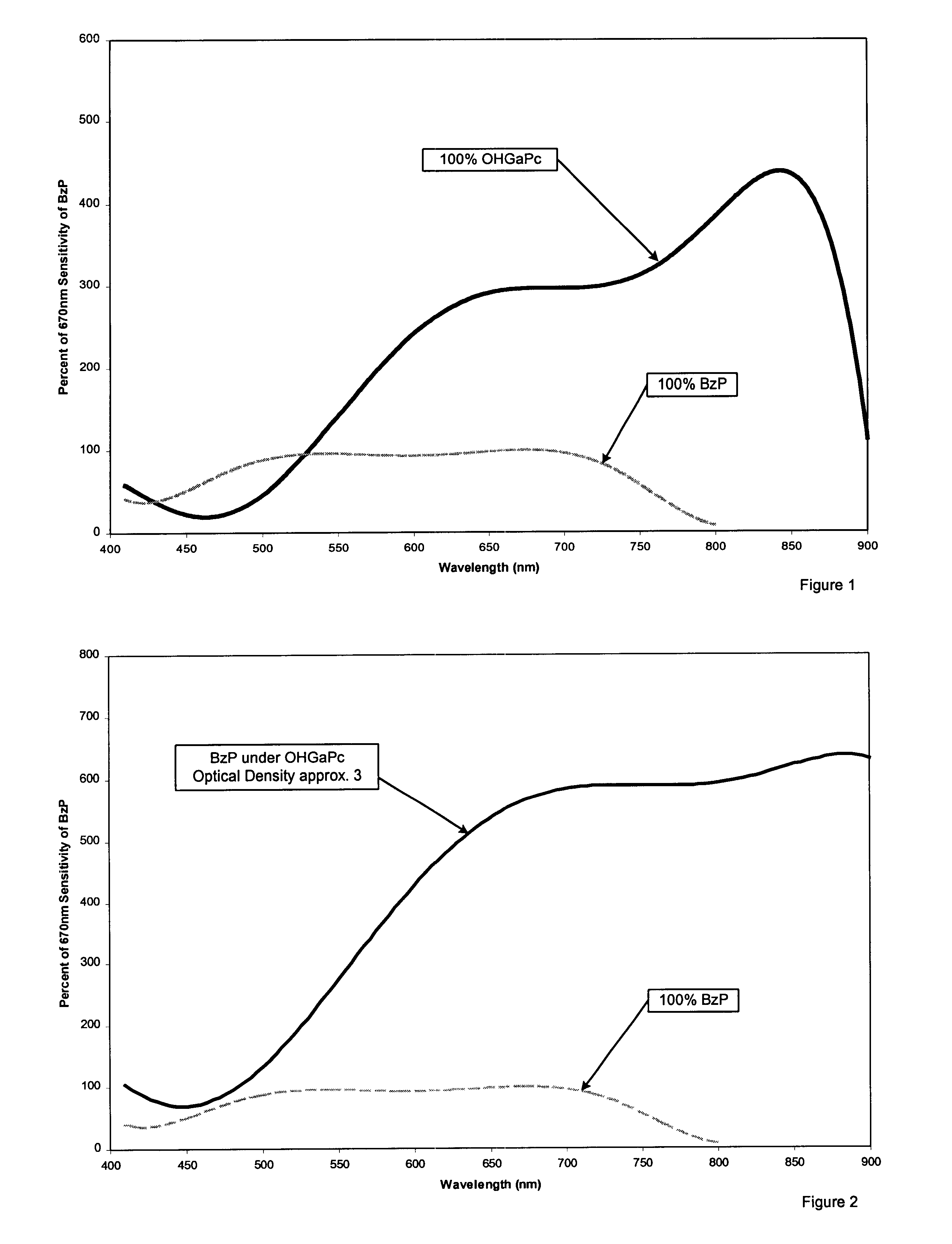
A BZP charge generation section dispersion is prepared by introducing 0.45 grams of Iupilon200 (PCZ-200) available from Mitsubishi Gas Chemical Corp. and 50 ml of tetrahydrofuran into a 4 oz. glass bottle. To this solution is added 2.4 grams of BZP and 300 grams of 1 / 8 inch (3.2 millimeter) diameter stainless steel shot. This mixture is then placed on a ball mill for 72 to 96 hours. Subsequently, 2.25 grams of PCZ-200 is dissolved in 46.1 grams of tetrahydrofuran and then added to the BZP slurry. This slurry is then placed on a shaker for 10 minutes.

A HoGaPC charge generation section dispersion is prepared by introducing 0.45 grams of Iupilon200 (PCZ-200) available from Mitsubishi Gas Chemical Corp. and 50 ml of tetrahydrofuran into a 4 oz. glass bottle. To this solution is added 2.4 grams of HoGaPC and 300 grams of 1 / 8 inch (3.2 millimeter) diameter stainless steel shot. This mixture is then placed on a ball mill for 20 to 24 hours. Subsequently, 2.25 grams of PCZ-200 is dissolved ...

example ii

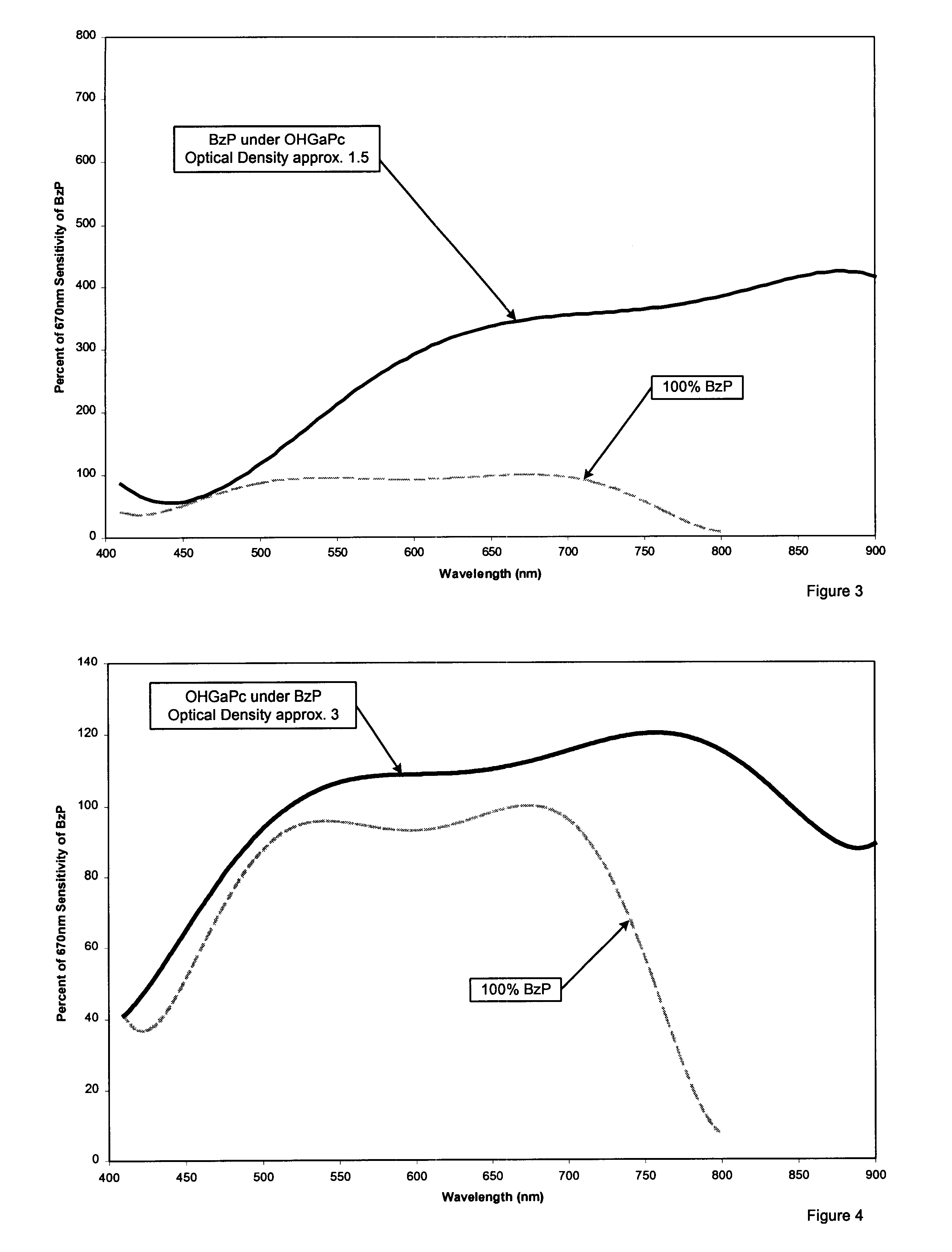
An electrophotographic imaging member is prepared identical to Example I, except the charge generation section dispersions are diluted by adding additional solvent to the charge generation section dispersions. The total optical density is 1.5. The sensitivity was normalized as in Example I and plotted in FIG. 3.


PUM


Abstract

An electrophotographic imaging member with a charge generation section having separate layers of benzimidazole perylene photoconductive pigment and hydroxygallium ptalocyanine photoconductive pigment.

Description

BACKGROUND OF THE INVENTION1. Field of InventionThis invention relates in general to electrophotographic imaging members and more specifically to an improved electrophotographic imaging member having a charge generation section comprised of layers of two different photoconductive pigments. The charge generation section is comprised of a layer of hydroxygallium phthalocyanine photoconductive pigment and a layer of benzimidazole perylene photoconductive pigment.2. Description of Related ArtIn the art of electrophotography, an electrophotographic plate comprising a photoconductive insulating layer on a conductive layer is imaged by first uniformly electrostatically charging the imaging surface of the photoconductive insulating layer. The plate is then exposed to a pattern of activating electromagnetic radiation such as light, which selectively dissipates the charge in the illuminated areas of the photoconductive insulating layer while leaving behind an electrostatic latent image in the...

Claims


Application Information

Patent Timeline
Patent Type & Authority Patents(United States)
IPC IPC(8): G03G5/047G03G5/043G03G5/06
CPCG03G5/047G03G5/0644G03G5/0646G03G5/0648G03G5/065G03G5/0696G03G5/0653G03G5/0655G03G5/0657G03G5/0659G03G5/0651
Inventor MISHRA, SATCHIDANANDHORGAN, ANTHONY M.CARMICHAEL, KATHLEEN M.NONKES, STEVEN P
Owner XEROX CORP
Why Eureka
Try Eureka