
Surfactant process for promoting gas hydrate formation and application of the same

a technology of surfactant and gas hydrate, which is applied in the direction of fixed capacity gas holders, mechanical equipment, gas/liquid distribution and storage, etc., can solve the problems of gas tank bursting, high cost and danger, and undesirable deficiencies of each of these storage methods

Inactive Publication Date: 2002-05-21
MISSISSIPPI STATE UNIVERSITY
View PDF3 Cites 122 Cited by
  • Summary
  • Abstract
  • Description
  • Claims
  • Application Information

AI Technical Summary

Benefits of technology

Another object of the invention is to simplify the process of gas hydrate formation and storage.

Problems solved by technology

Each of these means of storage, however, have undesirable deficiencies.
For example, liquified gas storage involves high costs and hazards such as the possibility of the gas tank rupturing.
Underground storage of natural gas is limited to the regions of the country with satisfactory geological features such as porous sandstone formations and salt domes.
Compressed gas storage, like liquified gas storage, involves high costs and hazards primarily because of the high pressures involved in storing gas in this manner.
Utilizing gas hydrates as a means to store natural gas or its components has not been practical because of numerous deficiencies.
First, the formation of hydrates in a quiescent system is extremely slow at hydrate-forming temperatures and pressures.
This decreases the rate of gas absorption into the free water and drastically slows the formation of hydrates.
Another deficiency in establishing a practical means of gas storage using hydrates results from the entrapment of free water (i.e., water not bound in hydrate form) between hydrate particles.
The entrapment of free water between solid hydrate particles has been a deterrent to practical use of hydrates because the result is inefficient packing of the gas which, in turn, results in a low storage capacity for the gas.
Yet another deficiency in using hydrates for storing gas is the complexity of the hydrate formation-storage-decomposition process.
The thickness of the slurry makes mechanical stirring difficult.
This separation and packaging step requires an often difficult and economically unfeasible mechanical process.

Method used


Image

  • Surfactant process for promoting gas hydrate formation and application of the same
  • Surfactant process for promoting gas hydrate formation and application of the same
  • Surfactant process for promoting gas hydrate formation and application of the same

Examples


example 1

Hydrate Growth

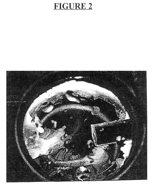
A quiescent water-surfactant-gas system is made by first combining about 2500 ml double distilled water and about 286 ppm sodium dodecyl sulfate to form a water-surfactant solution. The water-surfactant solution is pumped into the empty test cell to displace any gases therein. Ethane is then injected into the cell under pressure to displace the water-surfactant solution to a predetermined water level. The pressure of the test cell is about 2.31 MPa (335 psi). The temperature is adjusted to about 282 K (48.degree. F.). The inside of the cell is observed on a television monitor. Gas hydrates develop rapidly outwardly from the walls toward the center of the cell in the shape of a concentric cylinder.

FIG. 4 is a photograph of the crystal structure taken only six and a half minutes after the hydrate particles begin to form. As can be seen, the hydrate particles rapidly develop from the cell walls toward the center of the cell to form solid hydrate particle mass in the shape...

example 2

Rate of Hydrate Formation

A quiescent water-surfactant-gas system is made by first combining about 2500 ml double distilled water and about 286 ppm sodium dodecyl sulfate to form a water-surfactant solution. The water-surfactant solution is pumped into the empty test cell to displace any gases therein. Ethane is then injected into the cell under pressure to displace the water-surfactant solution to a predetermined water level. Hydrates form quickly, and about 0.3 moles ethane / liter solution is occluded in about 20 minutes after the induction period. The occluded gas content approaches equilibrium in about 3 hours. Thus, a formation-decomposition cycle, including turnaround time, can be achieved within a 24-hour period.

The results of Comparative Example 2 indicate that hydrates form very slowly in a quiescent system of pure water and gas. The results of Example 2 indicates that, under like conditions, the addition of surfactant to the water increases the rate of hydrate formation in a...

example 3

Conversion of Interstitial Water

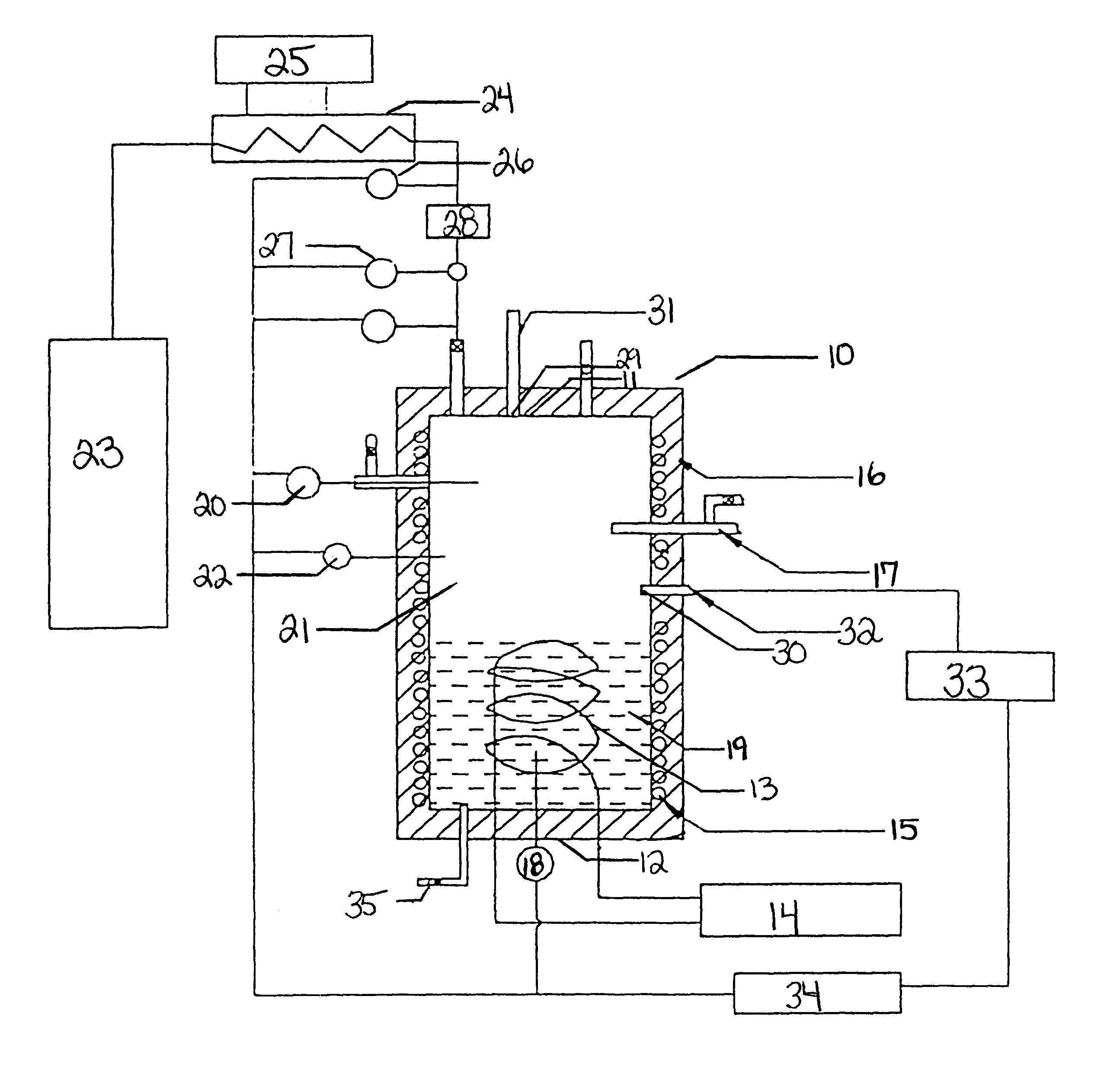
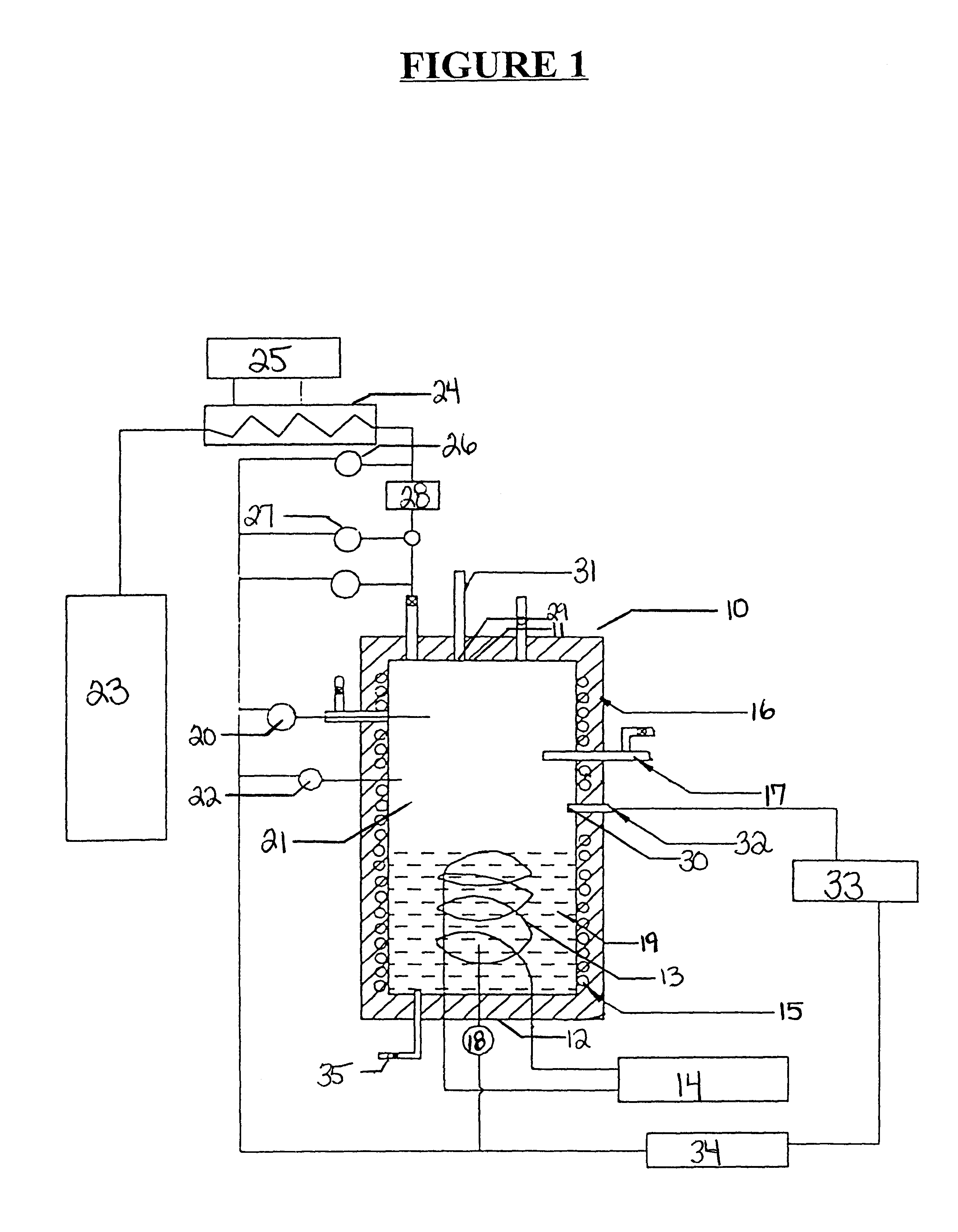
A quiescent water-surfactant-gas system is made by first combining about 2500 ml double distilled water and about 286 ppm sodium dodecyl sulfate to form a water-surfactant solution. The water-surfactant solution is pumped into the empty test cell to displace any gases therein. Ethane is then injected into the cell under pressure to displace the water-surfactant to a predetermined water level. The initial pressure is about 2.61 MPa (379 psi). Hydrate particles form with attendant free water trapped between particles. The ethane gas E-15 above the stagnant water is allowed to approach equilibrium at about 0.78 MPa (113 psi) and about 276.5 K (38.degree. F.), at which time the reaction is stopped and the unreacted free water is drained from the bottom of the cell using drain 35 depicted in FIG. 1. The cell is repressurized to about 2.61 MPa (379 psi) by adding another batch of ethane to the cell. The pressure is allowed to decline as more hydrates form. ...


PUM


Abstract

This invention relates to a method of storing gas using gas hydrates comprising forming gas hydrates in the presence of a water-surfactant solution that comprises water and surfactant. The addition of minor amounts of surfactant increases the gas hydrate formation rate, increases packing density of the solid hydrate mass and simplifies the formation-storage-decomposition process of gas hydrates. The minor amounts of surfactant also enhance the potential of gas hydrates for industrial storage applications.

Description

Field of the InventionThe present invention relates to a process and a composition for promoting gas hydrate formation. The invention also relates to a process for storing gas using gas hydrates. This invention was developed as a result of a contract with the United States Department of Energy.DISCUSSION OF THE BACKGROUNDCurrent means of storing natural gas (i.e., gas compositions constituted primarily of methane but that may contain minor amounts of other components such as ethane, propane, isobutane, butane, and / or nitrogen) or any of its components include, for example, compressed gas storage, liquified gas storage, underground storage, and adsorption. Each of these means of storage, however, have undesirable deficiencies. For example, liquified gas storage involves high costs and hazards such as the possibility of the gas tank rupturing. Underground storage of natural gas is limited to the regions of the country with satisfactory geological features such as porous sandstone form...

Claims


Application Information

Patent Timeline
IPC IPC(8): F17C11/00
CPCF17C11/007
Inventor ROGERS, RUDY E.ZHONG, YU
Owner MISSISSIPPI STATE UNIVERSITY
Learn More