Inductive RF plasma source with external discharge bridge

a plasma source and discharge bridge technology, applied in the direction of electric discharge lamps, coatings, electric lighting sources, etc., can solve the problems of plasma contamination, considerable power dissipation in the icp hardware, erosion and plasma contamination, etc., and achieve the effect of improving the efficiency of plasma generation inside the chamber

Inactive Publication Date: 2002-05-21
ADVANCED ENERGY IND INC
View PDF1 Cites 194 Cited by
  • Summary
  • Abstract
  • Description
  • Claims
  • Application Information

AI Technical Summary

Benefits of technology

An RF ICP source having a housing with a flanged cover. The interior of the housing serves for confining plasma generated by the plasma source. The cover has at least two openings which are connected by a hollow C-shaped bridge portion which is located outside the housing. The hollow C-shaped bridge portion is embraced by a ferrite core having a winding connected to an electric power supply source for generating a discharge current which flows through the bridge portion and through the interior of the housing. The discharge current is sufficient for inducing plasma in the interior of the housing which is supplied with a gaseous working medium. The

Problems solved by technology

The presence of electrodes can be a serious disadvantage in many applications because the electrodes may generate impurities in plasma volume and transfer them to the final product.
This means that the power transfer efficiency to the plasma in practical ICP devices is essentially less than 1, and considerable power is dissipated in the ICP hardware.
This high DC potential accelerates plasma ions to the window causing its erosion and plasma contamination.
This is an undesirable feature too, since energetic ions can damage the substrate 12.
Generally, the presence of high RF voltages on the coil 18 and on the matching device causes a lot of problems (such as corona discharge, sparking, and breakdown), and the elimination of these problems takes a significant and costly efforts.
Another common drawback of existing indus

Method used


Image

  • Inductive RF plasma source with external discharge bridge
  • Inductive RF plasma source with external discharge bridge
  • Inductive RF plasma source with external discharge bridge

Examples


Embodiment Construction

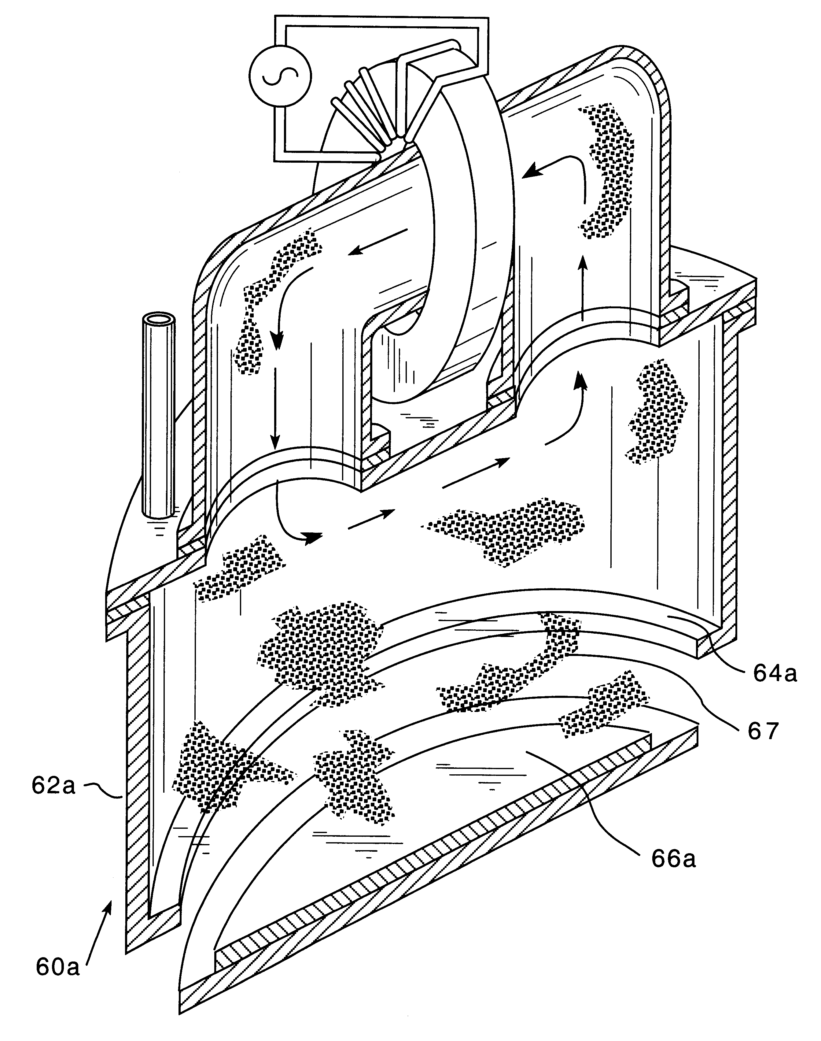
An RF plasma source 60 made according to one embodiment of the present invention is shown in FIG. 3 which is a three-dimensional sectional side view of the device. The device comprises a sealed cylindrical housing 62 with a bottom plate 64 for placing an object to be treated, e.g., a substrate 66 to be plasma processed, and a flanged cover 68. The housing 62 is sealed with an O-ring seal 70. The flanged cover 68 has a by-pass or bridge C-shaped portion 72 which extends upward, i.e., away from the working chamber or housing 62. A gaseous working medium is supplied into the housing 62 by a gas supply tube 74 via an opening 76 in the flanged cover 68. The bridge portion 72 is vacuum sealed against flanged cover 68 by ring-shaped seals 78a and 78b. The bridge portion 72 is surrounded by a ferrite ring-shaped transformer core 82 having a primary winding 84 connected to an RF power source 86. Ferrite core 82 induces an electromotive force (discharge voltage) inside bridge portion 72 As sh...


PUM

PropertyMeasurementUnit
Fractionaaaaaaaaaa
Flow rateaaaaaaaaaa
Currentaaaaaaaaaa

Abstract

An RF ICP source having a housing with a flanged cover. The interior of the housing serves for confining plasma generated by the plasma source. The cover has at least two openings which are connected by a hollow C-shaped bridge portion which is located outside the housing. The hollow C-shaped bridge portion is embraced by an annular ferrite core having a winding connected to an electric power supply source for generating a discharge current which flows through the bridge portion and through the interior of the housing. The discharge current is sufficient for inducing plasma in the interior of the housing which is supplied with a gaseous working medium. The power source operates on a relatively low frequency of 60 KHz or higher and has a power from several watt to several kilowatt. In order to provide a uniform plasma distribution and uniform plasma treatment, the cover may support a plurality of bridges. Individual control of the inductors on each bridge allows for plasma redistributing. The housing of the working chamber can be divided into two section for simultaneous treatment of two objects such as semiconductor substrates. A plate that divides the working chamber into two sections may have ferrite cores built into the plate around the bridges. In another embodiment, the flow of gaseous working medium is supplied via a tube connected to the bridge portion of the source.

Description

The present invention relates to a plasma processing technology, in particular to an RF inductive coupled plasma source with an external discharge bridge.Plasma is highly ionized gas containing an equal number of positive ions and electrons.At the present time plasma sources find wide applications in various fields of technology, in particular in the manufacture of semiconductor devices, e.g., for cleaning, etching, deposition, etc., in the production of semiconductor chips.There exist a great variety of plasma sources which differ in the methods of plasma excitation and the geometry of the electrodes and plasma volume, which, in turn, determine major parameters of the plasma. One type of plasma sources of this type which exists within this variety is known as an inductive coupled plasma. The plasma source of this type is excited by electromagnetic fields having frequencies within the range of few MHz to tens of MHz (RF frequencies).RF inductive coupled plasma sources (hereinafter r...

Claims


Application Information

Patent Timeline
IPC IPC(8): H01J37/32
CPCH01J37/321
Inventor SHUN'KO, EVGENY V.
Owner ADVANCED ENERGY IND INC
Why Eureka
Try Eureka