Lubricating device

a lubricating device and lubricating oil technology, which is applied in the direction of positive displacement liquid engines, manufacturing tools, machines/engines, etc., can solve the problems of increasing the torque of the bearing and the temperature of the bearing, affecting the operation environment, and affecting the performance of the bearing, so as to reduce the generation of noise, reduce the increase of torque and bearing, and the effect of high torque stability

Inactive Publication Date: 2002-06-04
NSK LTD
View PDF19 Cites 30 Cited by
  • Summary
  • Abstract
  • Description
  • Claims
  • Application Information

AI Technical Summary

Benefits of technology

to provide a lubricating device which injects a high-precision set fine quantity of lubricant onto the lubricating surface of a rotary body at a high speed to thereby minimize an increase in torque and bea...

Problems solved by technology

Firstly, in the lubricating device of an oil mist type, due to use of the compressed air, not only there arises a noise problem but also the mist-like lubricating oil scatters into the air to worsen an operation environment. Also, because of the scattering of the mist-like lubricating oil into the air, the quantity of lubricating oil to be supplied to the interior portion of the bearing is indefinite. Especially, in case where the bearing is rotated at a high speed, due to the effect of an air curtain, when dm.multidot.N is equal to or larger than 2000000 (dm expresses the pitch circle diameter of the bearing, and N expresses the rotation speed (rpm) of the bearing), the lubricating oil can be little supplied to the interior portion of the bearing, thereby raising a fear that the bearing can cause seizure.
In the lubricating device of an oil-air type, similarly to the-above-mentioned oil mist type lubricating device, since the compressed air is used, not only there arises a noise problem but also the mist-like lubricating oil scatters into the air to thereby worsen the operation environment.
Therefore, similarly, the lubricating oil can be little supplied to the interior portion of the bearing, thereby raising a fear that the bearing can cause seizure.
Also, in the lubricating device of an oil-air type, because it is difficult to supply a fine amount of lubricating oil continuously and stably, the lubricating oil must be supplied intermittently and thus the lubricating oil is supplied at a given quantity (normally, in the range of 0.01-0.03 cc) every given interval time (normally, in the rage of 8-16 min.) into the air pipe.
Therefore, since the quantity of lubricating oil to be supplied to the interior portion of the bearing varies every given time, the lubricating condition of the interior portion of the bearing varies all the time and, especially,...

Method used


Image

  • Lubricating device
  • Lubricating device
  • Lubricating device

Examples


first embodiment

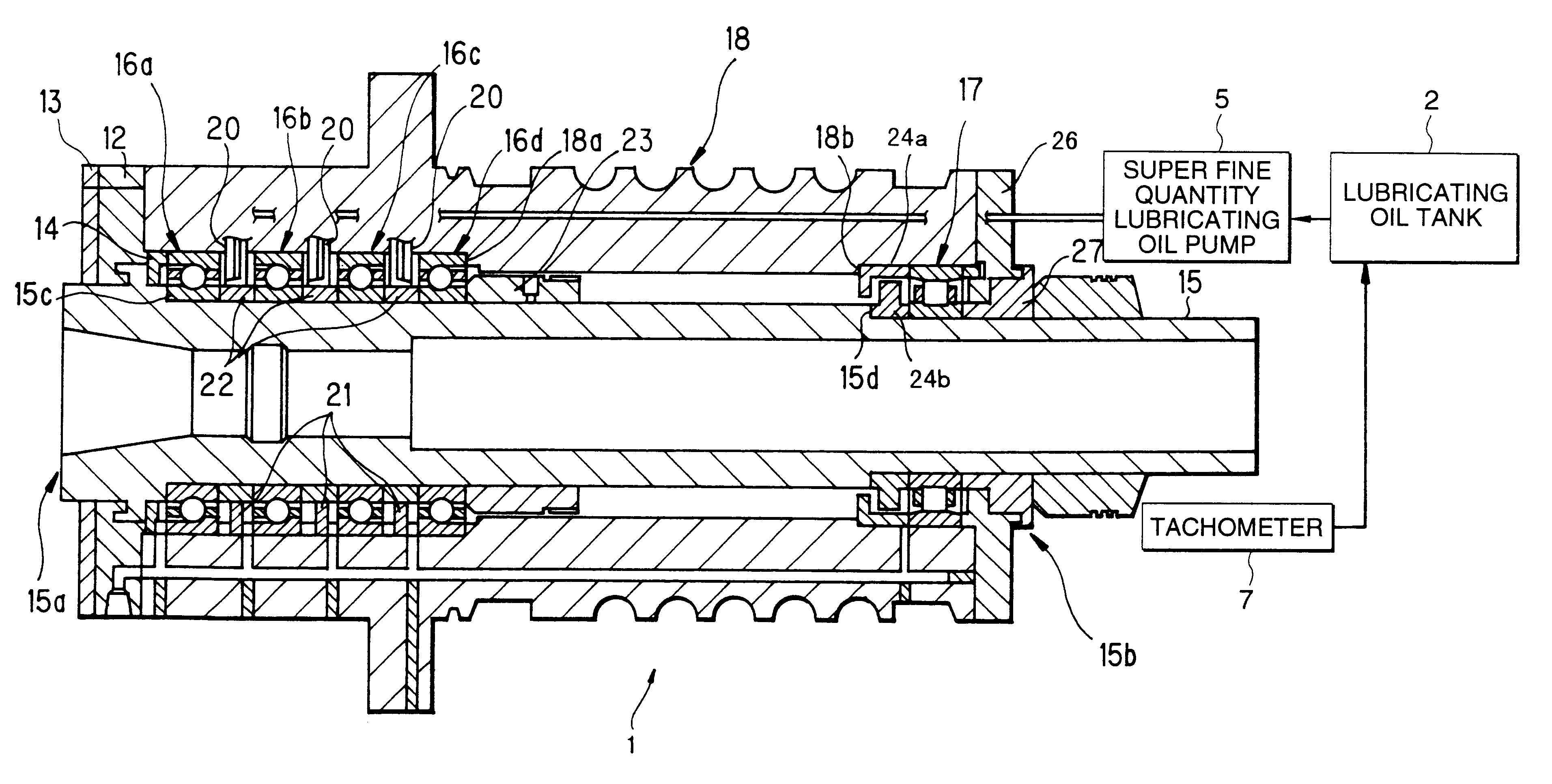
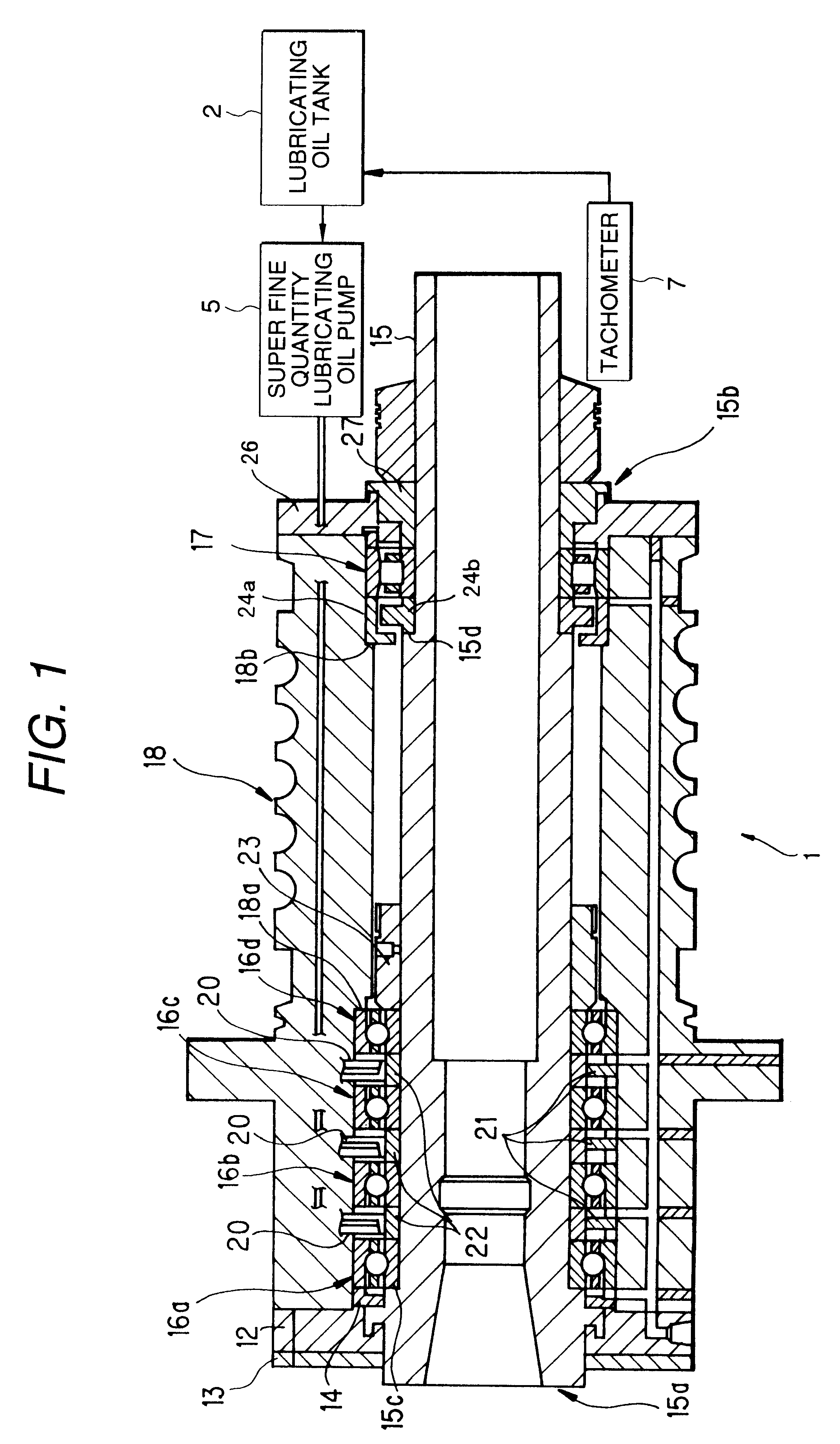
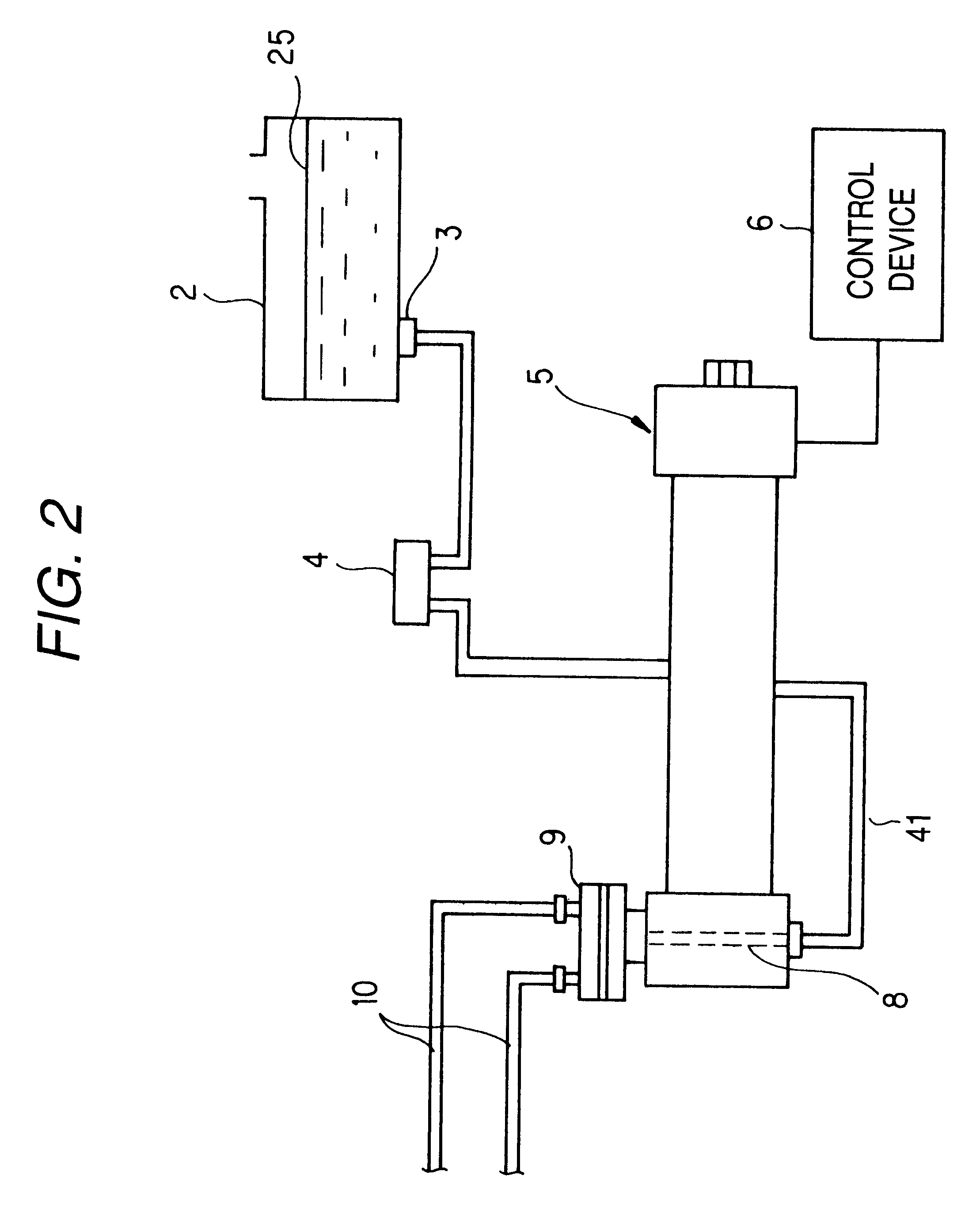
FIGS. 1 and 2 show the structure of a spindle apparatus according to a first embodiment of the invention. The spindle apparatus 1 comprises bearings for spindle 16a, 16b, 16c, 16d and 17 respectively shown in FIG. 1 as well as a lubricating oil tank 2, a lubricating oil filter 3, an air bleed device 4, a super fine quantity lubricating oil pump 5, a control device 6 for controlling the super fine quantity lubricating oil pump 5, a clogging sensor (a pressure sensor) 8, a multi-branch piping device 9, and a pipe 10, respectively shown in FIG. 2 and a tachometer 7 (see FIG. 1).

FIG. 1 is a longitudinal section view of the internal structure of the spindle apparatus 1. As shown in FIG. 1, the spindle apparatus 1 comprises a plurality of angular ball bearings 16a, 16b, 16c and 16d respectively used to support the front portion 15a of a spindle 15 horizontally in a freely rotatable manner, a cylindrical roller bearing 17 for supporting the rear portion 15b of the spindle 15, and a housing...

second embodiment

Next, description will be given below of a second embodiment of a spindle apparatus including a super fine quantity lubricating oil pump composed of an electromagnet and a belleville spring according to the invention. By the way, a structure employed in the present embodiment is similar to that of the spindle apparatus according to the first embodiment except for a lubricating device, and thus the duplicate description thereof is omitted here.

In the case of a super fine quantity lubricating oil pump according to the first embodiment, as a drive source for driving a piston which is used to increase the pressure within a pressurizing chamber (pump chamber), as shown in FIG. 3, there is used the rod-shaped giant magnetostrictive material. As the material of this rod-shaped body, piezo-electric element can also be used depending on the lubricating conditions. A magnetic field or a voltage is applied to the giant magnetostrictive material or piezo-electric element which is connected to t...


PUM

PropertyMeasurementUnit
Lengthaaaaaaaaaa
Volumeaaaaaaaaaa
Volumetric flow rateaaaaaaaaaa

Abstract

A rod body 30 is formed of magnetostrictive material and includes one end portion 30 fixed, and a piston 35 is fixed to the other end portion 30b of the rod body 30. The piston 35 is slidably disposed within a cylinder 36 in which there is formed a pump chamber 37. A suction port 39 for sucking lubricating oil into the pump chamber 37 is formed in the cylinder 36, while a suction valve 40 for preventing the lubricating oil from flowing out from the suction port 39 is disposed in the suction port 39. In the cylinder 36, there is disposed a nozzle 20 which communicates with the pump chamber 37 and has a sectional area smaller than the lubricating oil passage sectional area of the suction valve 40. There is disposed a coil 43 outside the rod body 30 and, to the coil 43, there is connected a control device 6 for controlling the supply of a current to be supplied to the coil 43.

Description

1. Field of the InventionThe present invention relates to a lubricating device which discharges lubricating oil to a spindle apparatus provided in various high-speed rotary machines such as a machine tool and, especially, to the bearing of the spindle.2. Description of the Related ArtConventionally, in lubricating the bearing of a high-speed rotary spindle, normally, there are used lubricating devices of various types such as an oil mist type, an oil-air type, and a jet type.The lubricating device of an oil mist type comprises an oil tank, a pump, a plunger, a pressure divider, compressed air, an electromagnetic valve, and a nozzle; and, in this device, lubricating oil is turned into a fine mist-like form, it is delivered through an air pipe using the compressed air, and it is jetted out to the interior portion of the bearing.The lubricating device of an oil-air type comprises an oil tank, a pump, a distributor, a compressed air source, a plunger, and a nozzle; and, in this device, ...

Claims


Application Information

Patent Timeline
IPC IPC(8): B23Q11/12B23Q1/70B23Q1/00F04B17/03F16N7/38F16N7/00
CPCB23Q1/70B23Q11/123F04B17/03F16N7/38F16C33/6659Y10T409/303976F16C2322/39Y10T409/309352F16C19/163F16C19/546
Inventor OKAZAKI, YUKIYOSHINAWAMOTO, TAIKOUSUGIYAMA, KENICHIDAIROKUNO, SATOSHI
Owner NSK LTD
Why Eureka
Try Eureka