
Magnetooptical recording medium on which high-density information can be recorded and method of reproducing the recorded information

a recording medium and high-density technology, applied in the field of magnetooptical recording medium, can solve the problems of reducing the amplitude of the reproduced signal, the inability to obtain sufficient reproduced signal, and the limitation of the wavelength of the laser beam and the numerical aperture of the objective lens

Inactive Publication Date: 2002-06-04
CANON KK
View PDF17 Cites 25 Cited by
  • Summary
  • Abstract
  • Description
  • Claims
  • Application Information

AI Technical Summary

Benefits of technology

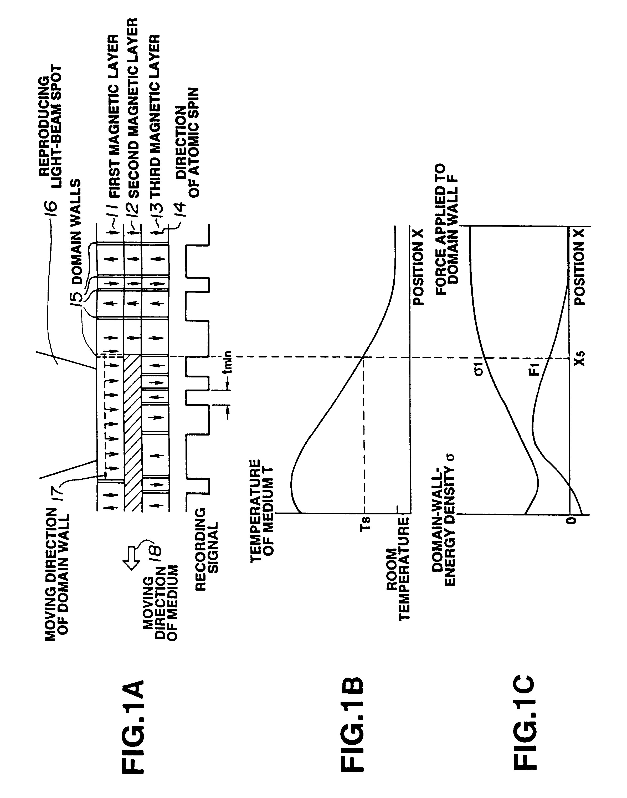
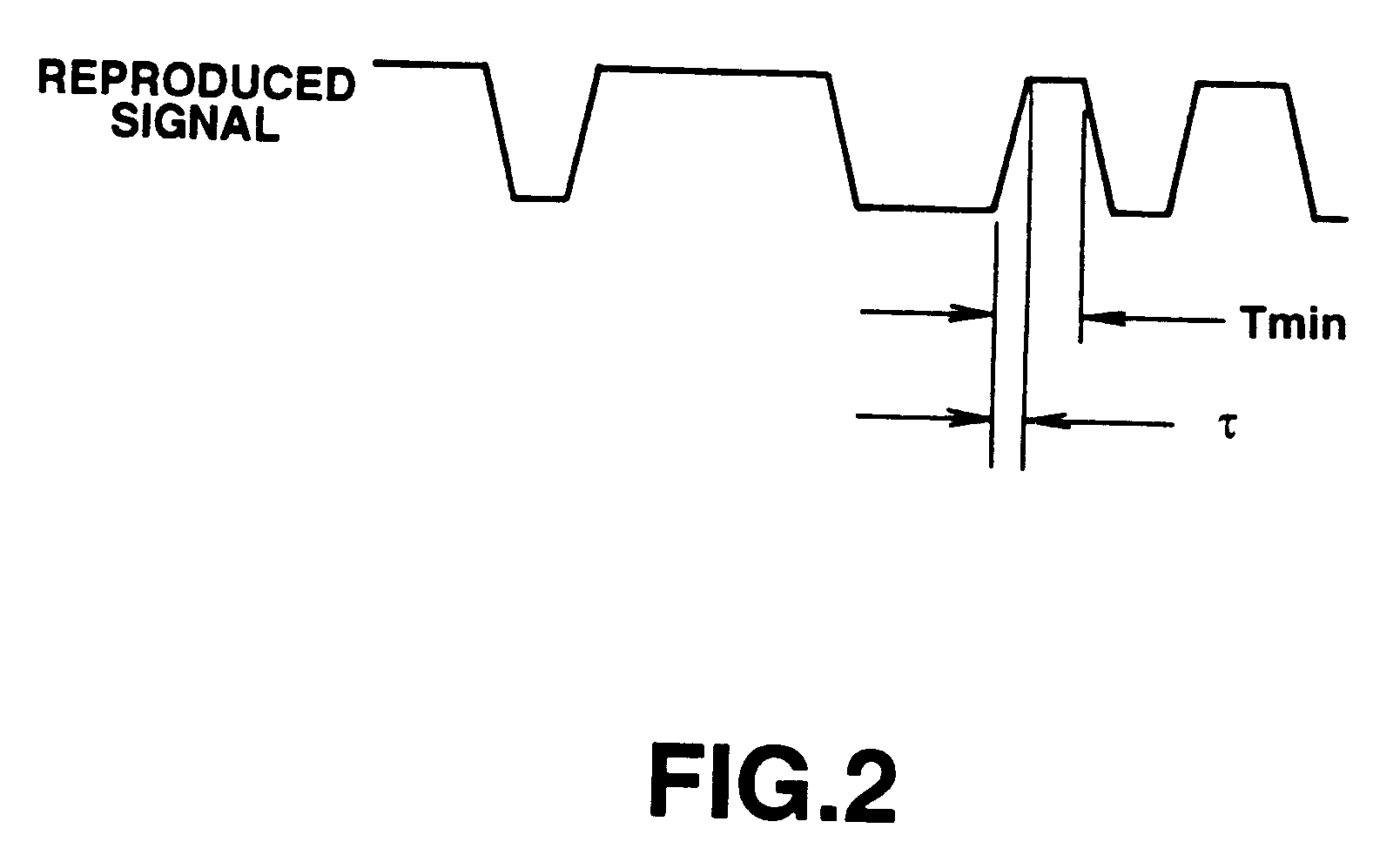
It is another object of the present invention to provide a magnetooptical recording medium and a method of reproducing information from the medium, in which a signal having a period equal to or less than the diffraction limit of light can be reproduced at a high speed without reducing the amplitude of the reproduced signal, so that the recording density and the transfer speed of the medium can be greatly increased, and the size of the reproducing apparatus can be reduced.

Problems solved by technology

However, there is a limitation in improving the wavelength of the laser beam and the numerical aperture of the objective lens.
However, in the magnetooptical reproducing method described in Japanese Patent Laid-open Application (Kokai) No. 3-93058 (1991), since the signal detection region which is effectively used is smaller than the spot size of the reproducing laser beam, the amplitude of the reproduced signal is greatly reduced, and therefore a sufficient reproduced signal cannot be obtained.
Hence, the above-described reproducing method has the problems that, for example, the magnetooptical recording apparatus has a complicated configuration, whereby the cost of the apparatus increases, and the size of the apparatus cannot be reduced.

Method used


Image

  • Magnetooptical recording medium on which high-density information can be recorded and method of reproducing the recorded information
  • Magnetooptical recording medium on which high-density information can be recorded and method of reproducing the recorded information
  • Magnetooptical recording medium on which high-density information can be recorded and method of reproducing the recorded information

Examples


experimental example 2

Each magnetooptical recording medium was prepared by forming thin films on a polycarbonate substrate using the same apparatus and method for forming films as in the case of the first experimental example. However, the forming method and the structure of the obtained medium were changed in the following three items.

First, an accelerated irradiation processing using Ar ions was performed for the surface of the substrate before forming the films. Second, an accelerated irradiation processing using Ar ions was performed for the surface of the film after forming the SiN layer, serving as the interference layer. The surface of the obtained medium was smoothed by the above-described processing. Thirdly, the thickness of the first magnetic layer was changed to 2000 angstroms. These changed items independently contribute to improvement in the mobility of domain walls of the first magnetic layer.

Recording / reproducing characteristics of the above-described medium was measured by the same metho...

experimental example 3

Each magnetooptical recording medium was prepared by forming thin films on a polycarbonate substrate using the same apparatus and method for forming films as in the case of the first experimental example.

In the present experimental example, however, prepits are formed on the substrate, and the cross section of the guide grooves has a U-like shape. Accordingly, the laminated magnetic layer is not separated at the guide groove portions.

A high-power laser beam was projected onto the guide groove portions to anneal the entire magnetic layer at the guide groove portions. As a result, the property of the magnetic layer at the guide groove portions changed to become a in-plane-magnetizing film, and the coupling between the magnetic layers on adjacent tracks was disconnected. Recording / reproducing characteristics of this medium were measured in the same manner as in the case of the first experimental example, and excellent results as in the case of the first experimental example were obtain...

experimental example 4

Recording / reproducing characteristics of the medium of the first experimental example were evaluated using substantially the same recording / reproducing apparatus as that used for the first experimental example.

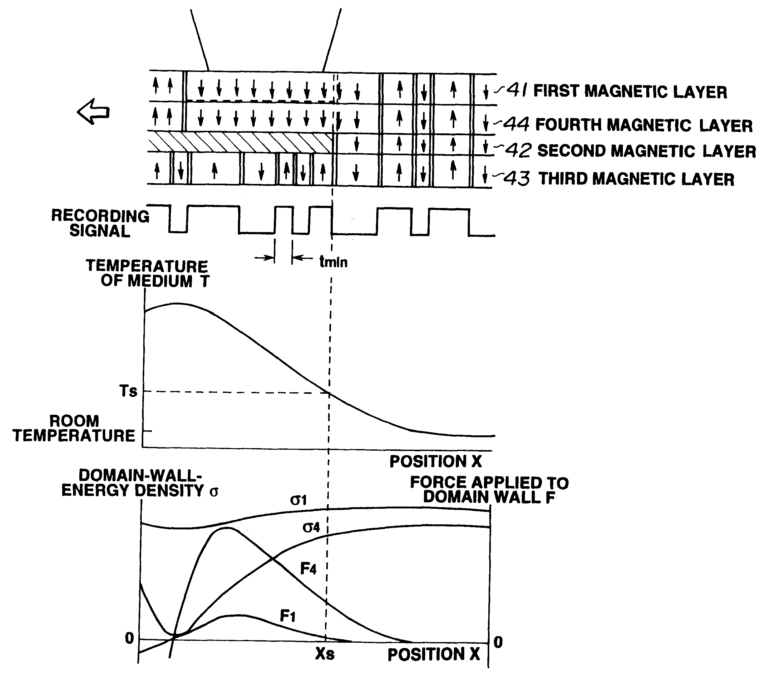
In this experimental example, however, the positional relationship between the recording / reproducing spot and the heating spot was changed as shown in FIG. 11A. That is, the recording / reproducing spot was arranged to be projected onto a portion corresponding to the slope in a front portion in the moving direction of the medium in the temperature distribution provided by the heating laser spot.

When the medium has moved and passed through the position S shown in FIG. 11A, the first magnetic layer and the third magnetic layer are coupled again, so that the oriented magnetized state of the third magnetic layer is transferred onto the first magnetic layer. When a domain wall in the third magnetic layer has passed through the position S, a domain wall is left at the position S in th...


PUM

PropertyMeasurementUnit
Curie temperatureaaaaaaaaaa
pressureaaaaaaaaaa
Curie temperaturesaaaaaaaaaa

Abstract

A magnetooptical recording medium includes a first magnetic layer, a second magnetic layer whose Curie temperature is lower than that of the first magnetic layer, and a third magnetic layer, comprising a vertically-magnetizing film, whose Curie temperature is higher than that of the second magnetic layer. The first magnetic layer, the second magnetic layer and the third magnetic layer are in a state of exchange coupling with each other at a portion of a vertically-magnetizing film. A domain walls formed in the first magnetic layer moves when the temperature of the medium has been raised to at least the Curie temperature of the second magnetic layer.

Description

1. Field of the InventionThis invention relates to a magnetooptical recording medium for recording / reproducing information using a laser beam utilizing a magnetooptical effect, and more particularly, to a magnetooptical recording medium on which high-density information can be recorded, and a method of reproducing the recorded information.2. Description of the Related ArtIn the field of rewritable high-density recording, magnetooptical recording media have attracted notice, in which information is recorded by writing magnetic domains on a magnetic thin film using the thermal energy of a semiconductor laser, and the information is read using a magnetooptical effect. Recently; there has been an increasing demand for large-capacity recording media by increasing the recording density of the magnetooptical recording media.The track recording density of an optical disk, such as a magnetooptical disk or the like, greatly depends on the wavelength of the laser beam used in the reproducing o...

Claims


Application Information

Patent Timeline
Patent Type & Authority Patents(United States)
IPC IPC(8): G11B11/00G11B11/105
CPCG11B11/10506G11B11/10508G11B11/10515G11B11/10528G11B11/10582G11B11/10584G11B11/10586G11B11/10543G11B11/10504Y10T428/24942G11B11/10593Y10S428/90
Inventor SHIRATORI, TSUTOMUHIROKI, TOMOYUKI
Owner CANON KK
Learn More