Implant for treating ailments of a joint or a bone

a technology for joints and bones, applied in the field of implants or prostheses, can solve the problems of complicated operation, complicated operation, and damage to or degeneration of the scaphoid

Inactive Publication Date: 2002-08-20
TORNIER SA SAINT ISMIER
View PDF16 Cites 204 Cited by
  • Summary
  • Abstract
  • Description
  • Claims
  • Application Information

AI Technical Summary

Benefits of technology

It is an object of the present invention to provide an implant or prosthesis wh

Problems solved by technology

Such an implant may replace a defective and painful joint or bone.
The wrist is a very complicated joint since it consists, not of two bones rubbing against one another, but of eight or nine principal bones of unusual shapes held and moving in equilibrium under control of a highly developed system of ligaments.
Other ailments too, besides fractures, can lead to damage to or degeneration of the scaphoid.
This prosthesis has the drawback that complicate operations have to be carried out in order to appropriately fix it to the neighboring bones and ligaments.
Furthermore, the material used to manufacture the prosthesis, namely vitallium, could wear away bones during movements made by the patient, as explained below.
It is not actually straightforward to determine the appropriate combination of shape, size and material enabling a suitable prosthesis to be produced for use in treating ailments of a joint or a bone.
For example, the present inventors have fou

Method used


Image

  • Implant for treating ailments of a joint or a bone
  • Implant for treating ailments of a joint or a bone
  • Implant for treating ailments of a joint or a bone

Examples


first embodiment

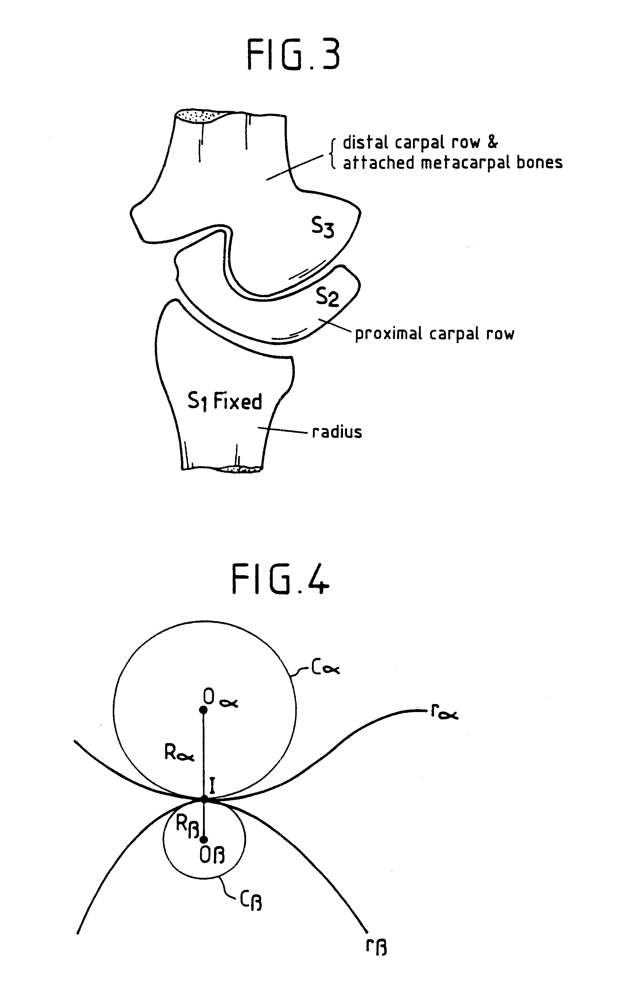
FIG. 7 shows the shape of conjugated surfaces J.sub.1, J.sub.2 in a gear having internal contact and illustrates the analogy between the teeth of such a gear and that portion of the solid S2 which corresponds to the scaphoid. It can be considered that the hatched portions of the gear tooth and the solid S2 correspond to the scaphoid. The prosthesis of the present invention is designed to replace that portion of the scaphoid indicated by the cross-hatched portion of the solid S2. In practice, the surface of the radius facing this portion of the scaphoid is not smooth but bowed inwards, such that the prosthesis according to the invention can be considered to correspond to the extremity of the tooth represented by the surface J.sub.2.

Accordingly, the prosthesis of the present invention is designed to have a portion having a large radius of curvature (i.e. a flatter portion) corresponding to the conjugated profile of the scaphoid facing the radius and, for similar reasons, to have a por...

second embodiment

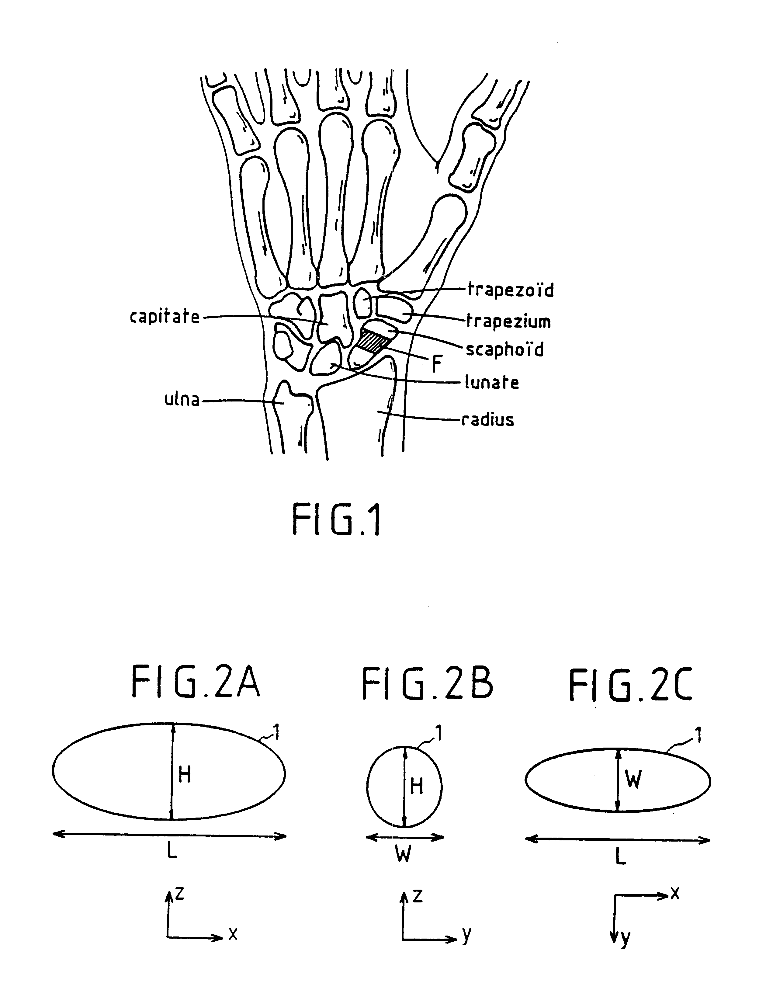
According to the invention, illustrated in FIGS. 10A, 10B, the implant, denoted by reference numeral 2, exhibits an oval first plane section (FIG. 10A) and a second plane section, perpendicular to the first plane section, which takes the form of a disc (FIG. 10B). The contour of the oval plane section is composed of arcs of circles, and more specifically of a first pair of facing arcs of circles having respective radii of curvature R1 and R2, and a second pair of facing arcs of circles having respective radii of curvature R3 and R4, with R1 and R2 being greater than R3 and R4. In the example as shown in FIGS. 10A, 10B, the radii R1 and R2 are equal to each other, as well as radii R3 and R4.

third embodiment

According to the invention, illustrated in FIGS. 11A, 11B, 11C, the implant, denoted by reference numeral 3, has a first surface portion 30 whose intersection with each one of the perpendicular planes (x,z), (y,z) is concave, and a second surface portion 31, facing the first portion 30, whose intersection with each one of the perpendicular planes (x,z) and (y,z) is also concave. The implant 3 further comprises two lateral surface portions 32, preferably substantially curved, connecting the surface portions 30 and 31 to each other. In plane section in the plane (x,y), the implant 3 exhibits an oval or substantially elliptic shape. By "substantially elliptic", it is meant that this plane section may be elliptic, almost elliptic, circular or composed of arcs of circles.


PUM

PropertyMeasurementUnit
Pressureaaaaaaaaaa
Pressureaaaaaaaaaa
Lengthaaaaaaaaaa

Abstract

The implant has at least one contact surface portion, made of pyrolytic carbon, designed to be in mobile contact with at least one bony surface when the implant is implanted in a patient. Furthermore, the implant is free from any attaching means, so that it remains free with respect to the at least one bony surface when implanted in the patient.

Description

The present invention generally relates to an implant intended to be implanted between bony surfaces of a patient. Such an implant may replace a defective and painful joint or bone.According to a particular application of the invention, the implant is used for treating ailments of the scaphoid (os scaphoideum).The scaphoid is one of the eight or nine principal bones forming part of the wrist in humans. The wrist is a very complicated joint since it consists, not of two bones rubbing against one another, but of eight or nine principal bones of unusual shapes held and moving in equilibrium under control of a highly developed system of ligaments. The scaphoid is of particular importance clinically because it is the wrist bone which tends most often to be fractured.The scaphoid is the largest of the bones located in the first row of wrist bones (known as the first carpal row or proximal carpal row). The other principal bones in the proximal carpal row are the lunate, triangular and pisi...

Claims


Application Information

Patent Timeline
IPC IPC(8): A61F2/30A61F2/42A61F2/00A61F2/46
CPCA61B17/562A61F2/30721A61F2/30767A61F2/42A61F2/4261A61L27/08A61F2/4202A61F2/442A61F2/4684A61F2002/30113A61F2002/30125A61F2002/3013A61F2002/30133A61F2002/30187A61F2002/30253A61F2002/30708A61F2002/30713A61F2002/30754A61F2002/3098A61F2002/30981A61F2002/4228A61F2002/423A61F2002/4233A61F2002/4235A61F2002/4243A61F2002/4248A61F2002/4251A61F2002/4256A61F2002/4258A61F2002/4264A61F2002/4276A61F2002/4287A61F2002/4289A61F2002/4663A61F2230/0006A61F2230/0008A61F2230/001A61F2230/0015A61F2230/0034A61F2230/0076A61F2250/0084A61F2250/0087A61F2310/00161A61F2310/00173A61F2310/00574A61F2310/0058A61F2/3094A61F2002/3071
Inventor HASSLER, MICHELPEQUIGNOT, JEAN-PIERREREAL, CECILEHUET, OLIVIER
Owner TORNIER SA SAINT ISMIER
Why Eureka
Try Eureka